Fiber optic connector and method of assembling the same

Active Publication Date: 2016-12-08
COMMSCOPE TELECOMM (SHANGHAI) CO LTD
View PDF0 Cites 19 Cited by
  • Summary
  • Abstract
  • Description
  • Claims
  • Application Information

AI Technical Summary

Benefits of technology

[0016]According to an object of the present invention, there is provided a fiber optic connector and a method of assembling the fiber optic connector, wherein a ferrule assembly, a spring and a spring seat are adapted to be pre-assembled to an integral cable assembly having a profile size less than that of a connector housing. In this way, the cable assembly with less profile size may be easily pulled through an elongated pipe in the field. Furthermore, after pulled through the elongated pipe, the cable assembly as a whole may be quickly assembled into the connector housing in the field.
[0017]According to another object of the present invention, there is provided a fiber optic connector and a method of assem

Problems solved by technology

In addition, it is necessary to use various expensive apparatus, for example, high precision cutting tool, splicing machine or the like, to perform the splicing of the optical fibers in the field.
If the cutting quality is poor, it decreases the coupling properties (including optical attenuation, echo, and long term reliability, etc.).
Furthermore, as for the cold coupling with the V-shaped or U-shaped groove, the coupling loss is increased with the variation of the temperature.
With the passage of time, because of the opened V-shaped or U-shaped groove, flowing away, pollution and aging occurring in the optical matching paste may cause the insertion loss to become larger or even reduce the optical signal to zero.
Thereby, the cold coupling has a poor stability and long-term reliability.
The way of assembling connector in field has a relatively high cost.
Also, because the optical matching paste is used, it has a poor stability and long-term reliabilit

Method used


Image

  • Fiber optic connector and method of assembling the same
  • Fiber optic connector and method of assembling the same
  • Fiber optic connector and method of assembling the same

Examples


Embodiment Construction

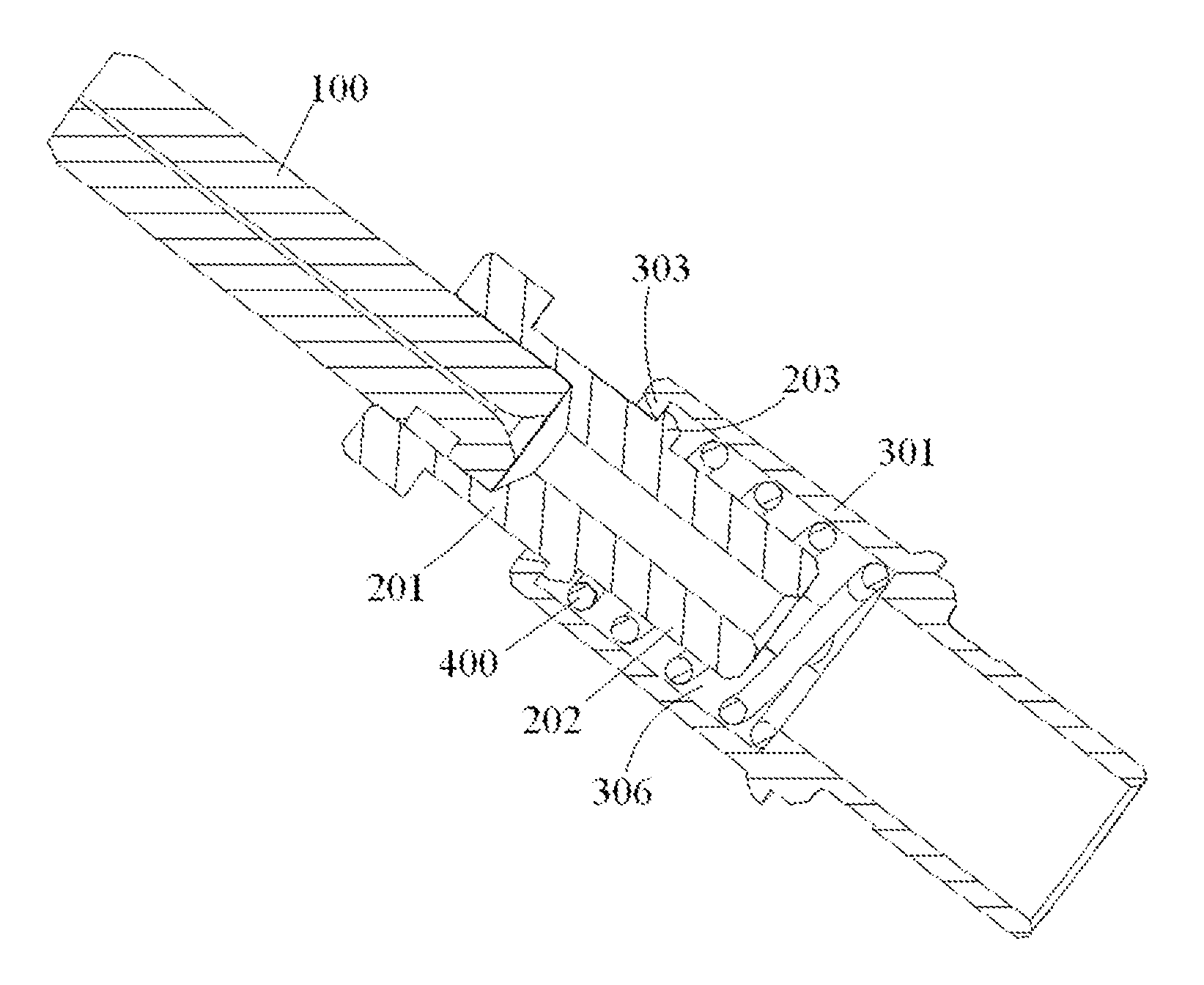
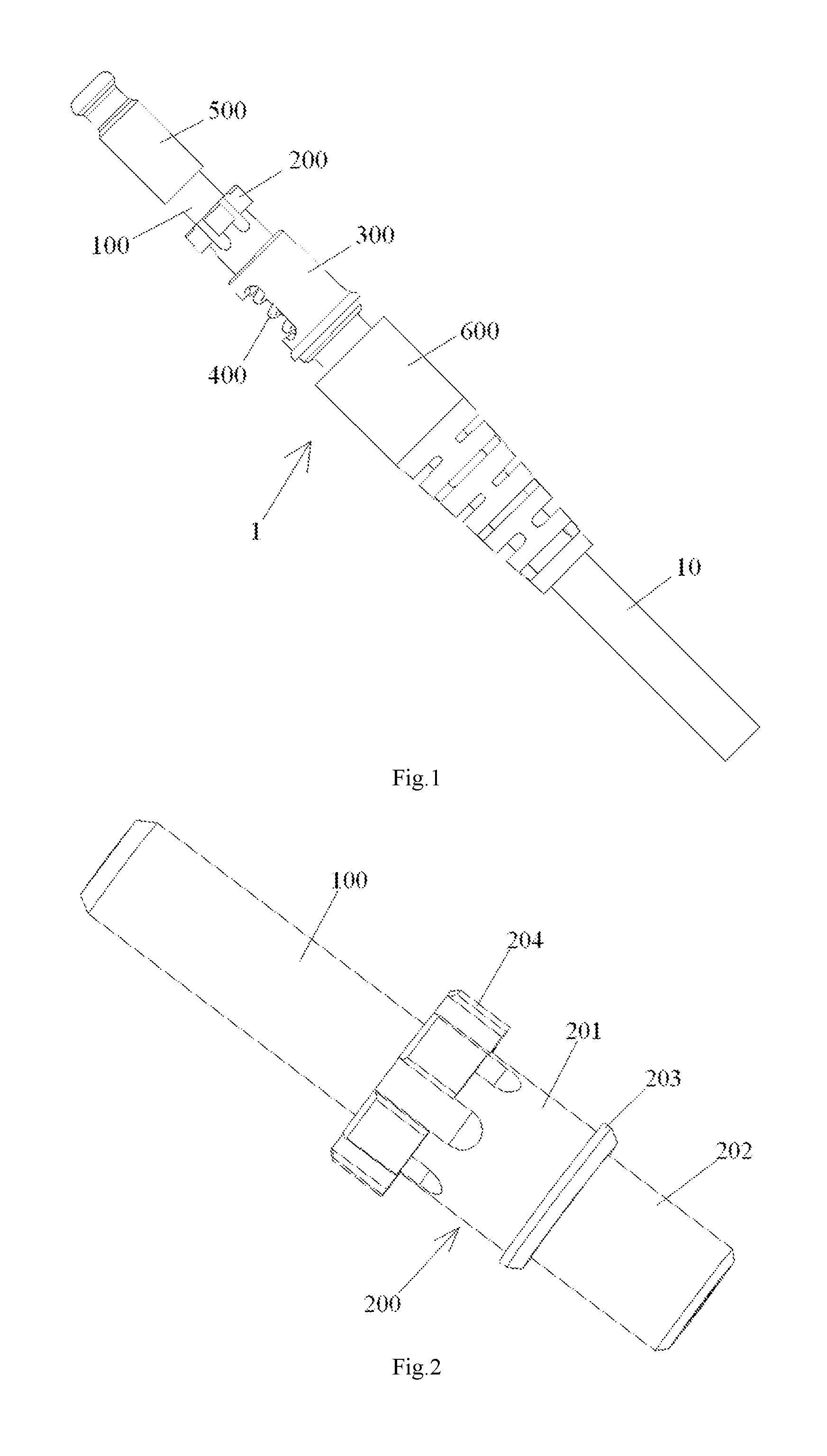
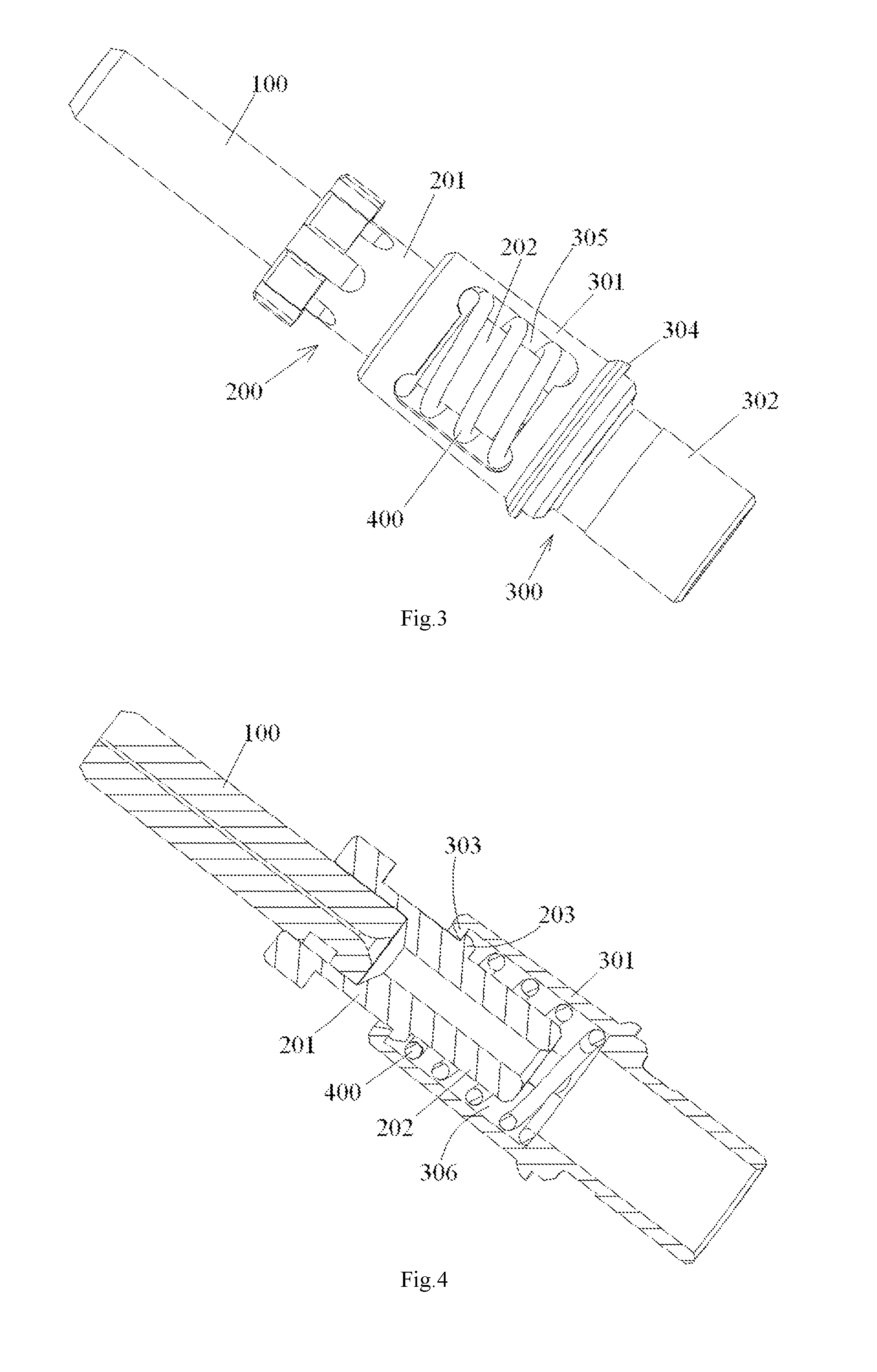
[0068]Exemplary embodiments of the present disclosure will be described hereinafter in detail with reference to the attached drawings, wherein the like reference numerals refer to the like elements. The present disclosure may, however, be embodied in many different forms and should not be construed as being limited to the embodiment set forth herein; rather, these embodiments are provided so that the present disclosure will be thorough and complete, and will fully convey the concept of the disclosure to those skilled in the art.

[0069]In the following detailed description, for purposes of explanation, numerous specific details are set forth in order to provide a thorough understanding of the disclosed embodiments. It will be apparent, however, that one or more embodiments may be practiced without these specific details. In other instances, well-known structures and devices are schematically shown in order to simplify the drawing.

[0070]According to a general concept of the present inv...


PUM


Abstract

The present invention discloses a fiber optic connector comprises: a ferrule assembly; a spring seat provided behind the ferrule assembly; and a spring provided between the ferrule assembly and the spring seat. The spring seat has a receiving chamber having an insertion port through which a portion of the ferrule assembly is inserted into the receiving chamber; wherein the ferrule assembly is pre-assembled into the receiving chamber of the spring seat in a way that the ferrule assembly is held to be movably engaged with the spring seat. The spring is fitted and compressed in the receiving chamber. As a result, the ferrule assembly, the spring seat and the spring are pre-assembled into an integral assembly before being inserting into a connector housing. All components of the connector except for the housing may be smoothly pulled through a small long pipe as a whole. After being pulled through the pipe, all components of the connector except for the housing may be easily and quickly inserted into the housing as a whole at one time.

Description

CROSS-REFERENCE TO RELATED APPLICATION[0001]This application claims the benefit of Chinese Patent Application No. 201410051670.6 filed on Feb. 14, 2014 in the State Intellectual Property Office of China, the whole disclosure of which is incorporated herein by reference.BACKGROUND OF THE INVENTION[0002]Field of the Invention[0003]The present invention relates to a fiber optic connector and a method of assembling the fiber optic connector.[0004]Description of the Related Art[0005]In prior art, optical cables / fibers generally are optically coupled by following ways of:[0006]1) Splicing Optical Fibers in Field[0007]The way of splicing the optical cables / fibers generally comprises steps of: Firstly, processing ends of the optical fibers (including peeling off the optical cable, cleaning and cutting the optical fiber of the optical cable); Secondly, manually or automatically setting optimum splicing parameters of a splicing machine and relative positions of the optical fibers to be splice...

Claims


Application Information

Patent Timeline
IPC IPC(8): G02B6/38
CPCG02B6/3821G02B6/3849G02B6/3887G02B6/3869G02B6/3851G02B6/3888
Inventor LIU, LEITONG, ZHAOYANG
Owner COMMSCOPE TELECOMM (SHANGHAI) CO LTD
Why Eureka
Try Eureka