Injection device comprising at least one flexible diaphragm

a technology of flexible diaphragm and injection device, which is applied in the direction of domestic applications, other domestic articles, domestic objects, etc., can solve the problems of disc-shaped membranes unsuitable for liquid use, and achieve the effect of reducing the free portion and high pressur

Active Publication Date: 2016-12-15
DISCMA
View PDF2 Cites 3 Cited by
  • Summary
  • Abstract
  • Description
  • Claims
  • Application Information

AI Technical Summary

Benefits of technology

[0069]reducing the free portion of at least the closing diaphragm during or after said opening by decreasing the surface of the free portion of said diaphragm.
[0070]As mentioned previously, when a liquid is flowing through the outlet, the mechanical support of the closing diaphragm is increased, thereby ensuring that the closing diaphragm can endure high pressures.

Problems solved by technology

As mentioned above, in EP-1 762 539, the disc-shaped membrane adopts a conical shape in the opened position, which means that the membrane is stretched inside the main housing and remains unsupported in the opened position when liquid is injected, the surface of the free portion remaining the same when the movable part moves from the closed position to the opened position, which makes such a disc-shaped membrane unfit to be used when liquid is injected at a high pressure.

Method used


Image

  • Injection device comprising at least one flexible diaphragm
  • Injection device comprising at least one flexible diaphragm
  • Injection device comprising at least one flexible diaphragm

Examples


first embodiment

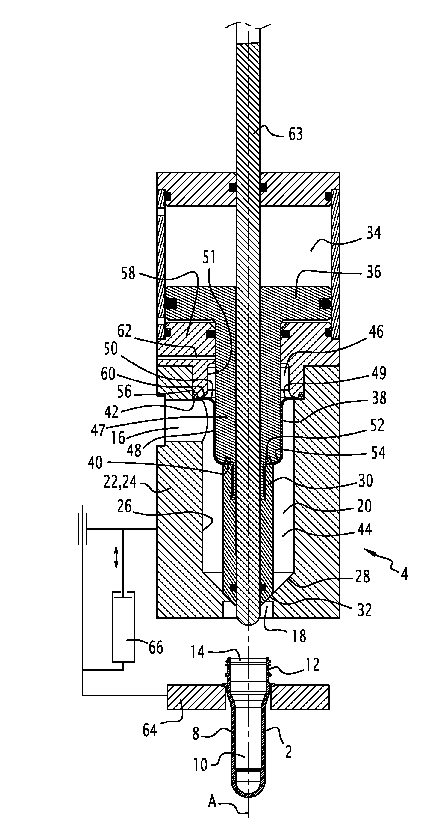
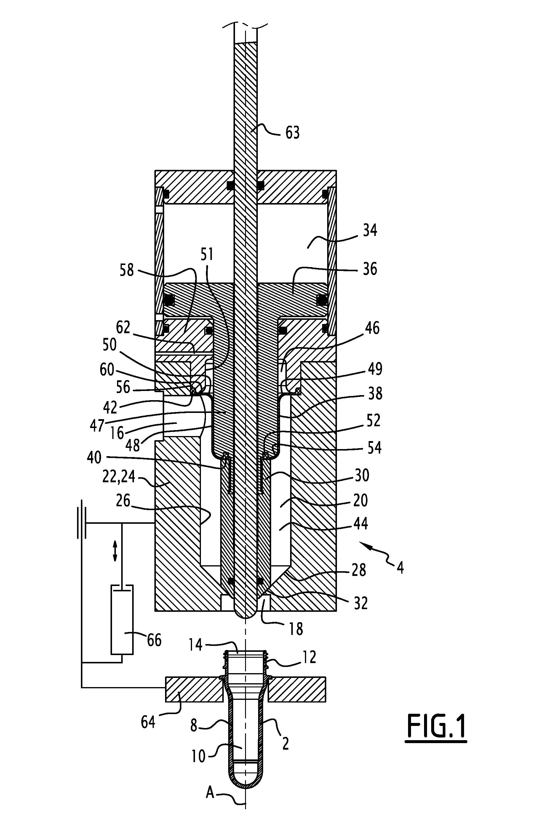
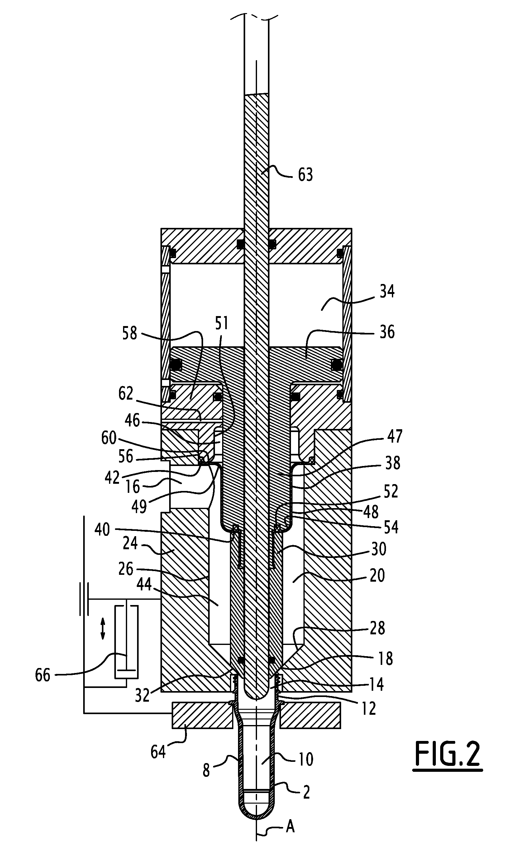
[0095]In reference to FIGS. 1 to 3, the injection device 4 for injecting the incompressible liquid in the preform 2 will be described.

[0096]The injection device 4 comprises a main housing 22 comprising, or defining, an inlet 16, an outlet 18 and an inner chamber 20 extending between the inlet 16 and the outlet 18 and placing the inlet 16 in fluidic communication with the outlet 18.

[0097]According to the first embodiment, the inlet 16, the outlet 18 and the inner chamber 20 are defined by a main body 24, forming the whole main housing 22, made of a single rigid block or is made of rigid elementary bodies rigidly fixed together, meaning that the main body 24 forms a single unit. The main body 24 is for example formed of a hollow casing.

[0098]The inlet 16 is intended to be placed in fluidic communication with an incompressible liquid source (not shown), for example a water reservoir, via injection means (not shown) adapted for transferring the liquid from the liquid source to the inlet...

second embodiment

[0140]The functioning of the injection device of the second embodiment will now be described. First, the injection device 68 is in a retracted configuration wherein the nozzle body 70 is in the retracted position and the closing body 30 is in the closed position, as shown in FIG. 4. In this configuration, the closing body 30 is in such a position that the closing diaphragm 38 is completely applied against the wall of the dry area 46 as when the closing body 30 is in the opened position. The nozzle diaphragm 76 is then mostly applied against the outside wall of the nozzle body 70, meaning that the supported surface is mainly formed by wall of the nozzle body 70. Only the part proximate to the second end 80 of the nozzle diaphragm 76 is applied against a part of the wall of the second rigid support body 75. Furthermore, in this position, the nozzle diaphragm 76 also comprises the free portion 79 which is not applied against any wall and which extends between the second rigid support b...

third embodiment

[0150] shown in FIG. 7, an injection device 101 may include actuation means of the closing body 30 provided downstream of the inlet 16, by making the piston 36 extend around the closing body 30 in a second actuation chamber 100 extending below the actuation chamber 74 of the nozzle body 70. Such an embodiment reduces the stroke of the piston 36, which simply has to be able to move the closing body 30 between its closed position and its opened position and does not have to comprise a part of the stroke for moving the closing body 30 with the nozzle body 70, when said nozzle body 70 moves from its retracted position to its active position, in order to maintain the closing body 30 in its closed position.

[0151]However, in such an embodiment, a third diaphragm 102 is needed to ensure the fluid tightness between the closing body 30 and the nozzle body 70. The third diaphragm 102 is like the closing diaphragm 38 and the nozzle diaphragm 76. One end 104 of the third diaphragm 102 is attache...


PUM

PropertyMeasurementUnit
pressureaaaaaaaaaa
pressureaaaaaaaaaa
areaaaaaaaaaaa

Abstract

An injection device having at least one flexible diaphragm The injection device for forming a preform into a container and filling the container, and further including a main housing having an inlet, an outlet and an injection chamber, a closing body movable relative to the outlet between a closed position and an opened position, a closing diaphragm attached at least to the closing body, the injection chamber being delimited at least by an inner surface of the closing diaphragm, the closing diaphragm having an outer surface defining an outside area, a bearing surface against which a supported portion of the outer surface of the closing diaphragm is applied. The closing diaphragm further includes a free portion forming with the supported portion the whole outer surface of the closing diaphragm. The bearing surface is arranged such that the surface of the free portion decreases when the closing body moves from the closed position to the opened position.

Description

CROSS-REFERENCE TO RELATED APPLICATIONS[0001]This application is the U.S. national phase of PCT Application No. PCT / EP2015 / 053129 filed on Feb. 13, 2015 and claims priority to European Application No. 14305274.4 filed on Feb. 26, 2014, the disclosures of which are incorporated in their entirety by reference herein.TECHNICAL FIELD[0002]The invention relates to an injection device for a forming and filling station for forming a container from a preform and filling said container using a pressurized liquid and filling said container.[0003]The invention also relates to a forming and filling station comprising such an injection device and an injection method using such an injection device and to a forming and filling method for forming a container from a preform using such an injection method.[0004]The invention relates to the field, known as hydro forming, of forming containers from a preform using an incompressible liquid to deform the preform.[0005]In the application, “liquid” has a p...

Claims


Application Information

Patent Timeline
Patent Type & Authority Applications(United States)
IPC IPC(8): B29C49/58B29C49/46
CPCB29C49/58B29C49/46B29K2067/003B29C2049/5831B29L2031/7158B29C2049/4664B29C49/06B29C2949/0715
Inventor GILLET, DENIS
Owner DISCMA
Why Eureka
Try Eureka