Wire harness

Active Publication Date: 2016-12-15
YAZAKI CORP +1
View PDF2 Cites 20 Cited by
  • Summary
  • Abstract
  • Description
  • Claims
  • Application Information

AI Technical Summary

Benefits of technology

[0007]The present invention has been conceived in view of the above description, and an object of

Problems solved by technology

When power is supplied from the inverter to the motor, an excessive surge voltage may be generated inside a wire harness that connects the inverter and the motor and input to the motor due to a steeply rising voltage contained in an output from the inverter.
Thus, as a whole length of the wire harness that connects the inverter

Method used


Image

  • Wire harness
  • Wire harness
  • Wire harness

Examples


embodiment

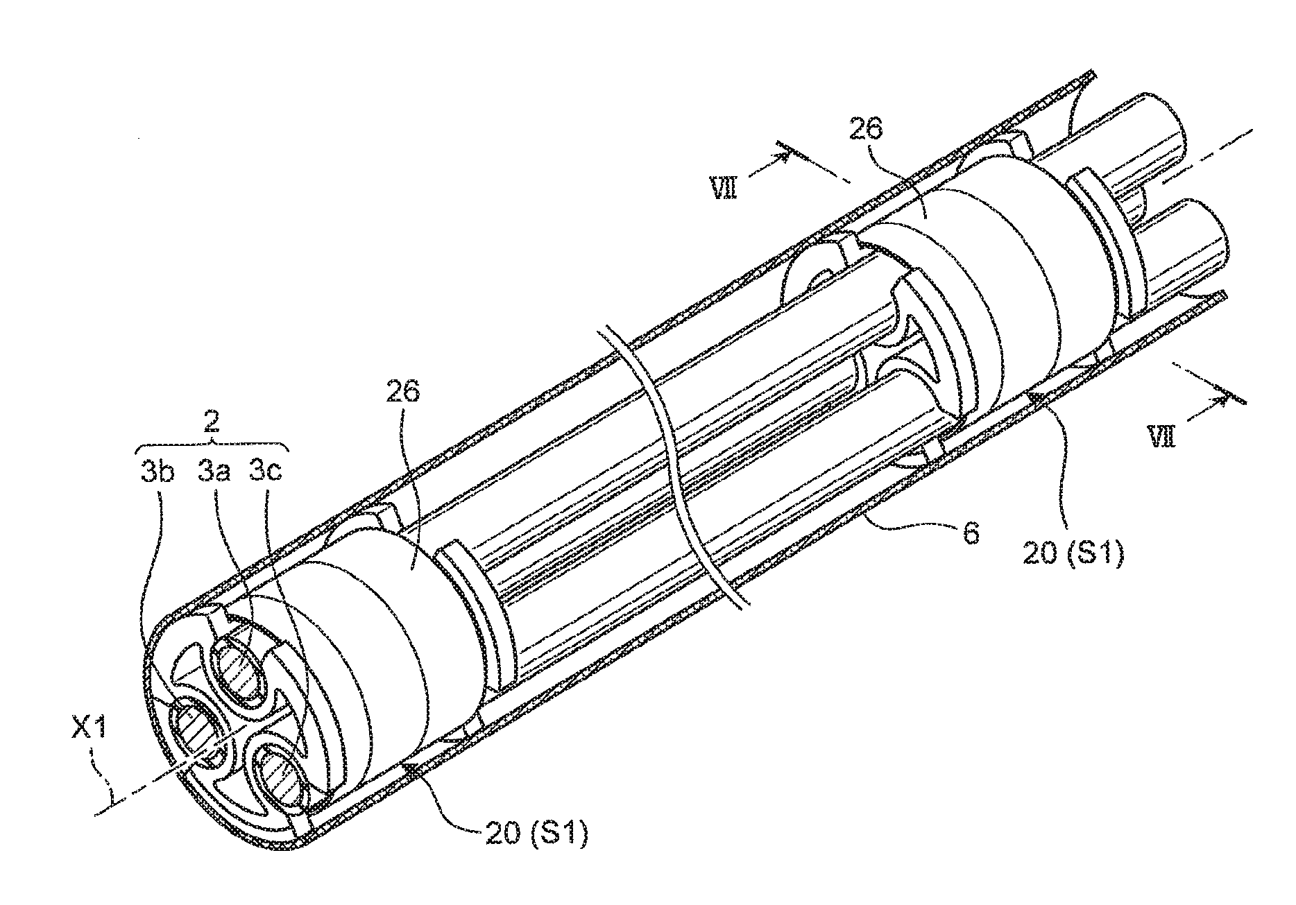
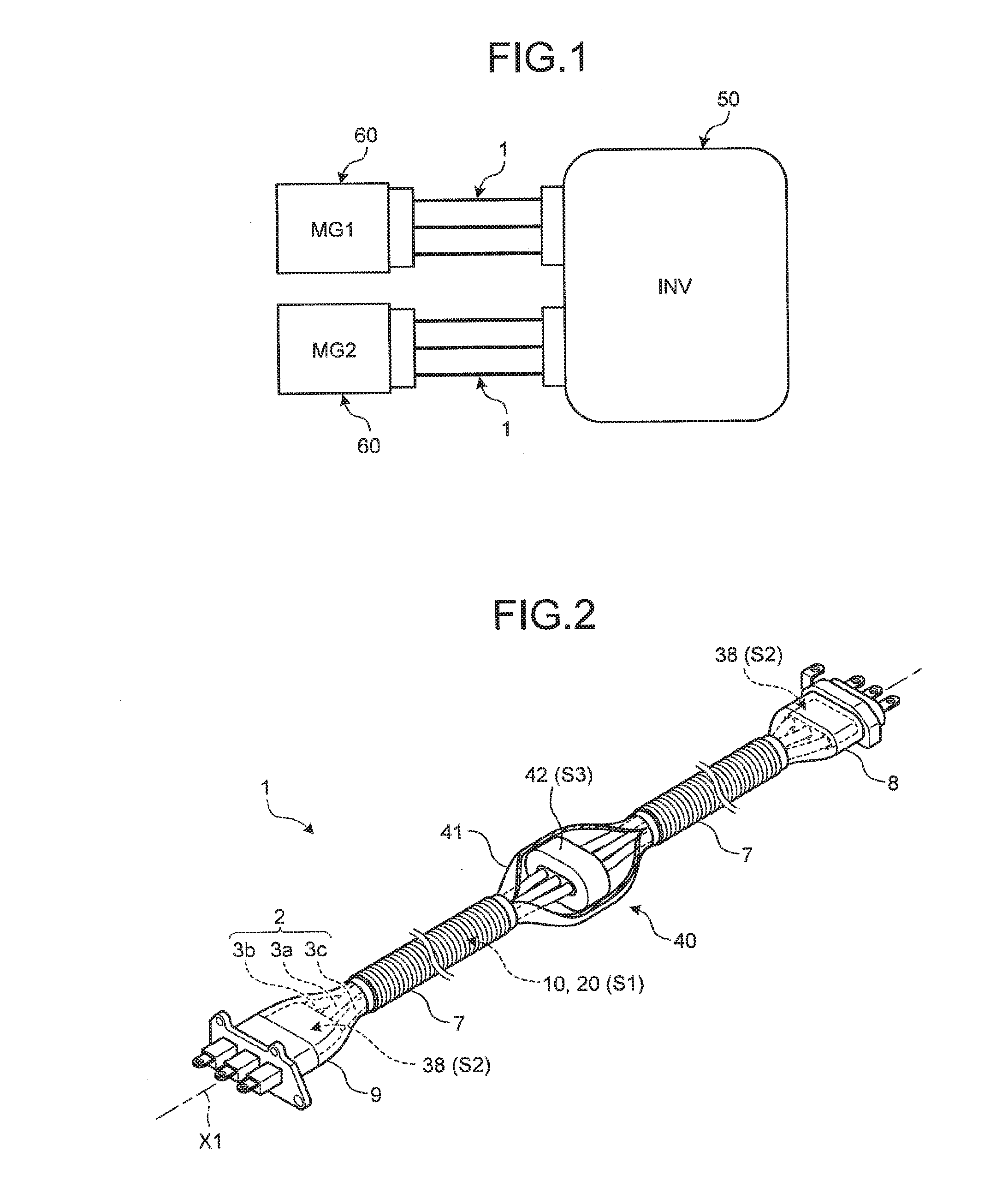
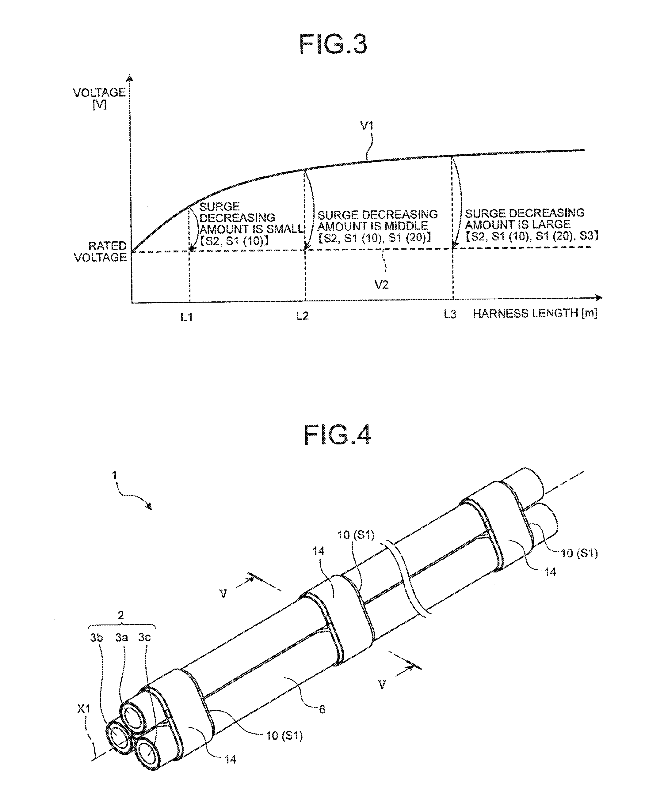
[0053]A description will be given of a schematic configuration of a wire harness 1 according to the present embodiment with reference to FIGS. 1, 2, and 5. FIG. 1 is a schematic diagram illustrating a configuration for connecting a motor and an inverter by a wire harness according to an embodiment of the present invention. FIG. 2 is a perspective view of the wire harness according to an embodiment of the present invention. FIG. 5 is a diagram illustrating an example of a cross section perpendicular to an axial direction of the wire harness according to an embodiment of the present invention.

[0054]An inverter 50 (“INV” of FIG. 1) and a motor 60 (“MG1” and “MG2” of FIG. 1) illustrated in FIG. 1 are installed in a vehicle such as a hybrid vehicle and an electric vehicle. The inverter 50 is a device for converting a direct current (DC) output from a power source (not illustrated) installed in the vehicle into a three-phase alternating current (AC) output. The inverter 50 may output a pu...


PUM


Abstract

A wire harness includes a wire portion having three wires arranged in the same direction, connectors connected to both end portions of the wire portion, a middle portion installed in an intermediate position of the wire portion between the connectors, a wire-side surge reducing section provided in the wire portion, a connector-side surge reducing section provided in each of the connectors, and a middle portion-side surge reducing section provided in the middle portion.

Description

CROSS-REFERENCE TO RELATED APPLICATION(S)[0001]The present application claims priority to and incorporates by reference the entire contents of Japanese Patent Application No. 2015-119639 filed in Japan on Jun. 12, 2015.BACKGROUND OF THE INVENTION[0002]1. Field of the Invention[0003]The present invention relates to a wire harness.[0004]2. Description of the Related Art[0005]In a conventional vehicle such as a hybrid vehicle and an electric vehicle, an inverter and a motor have been connected to each other through a three-phase wire, and power has been supplied from the inverter to the motor. When power is supplied from the inverter to the motor, an excessive surge voltage may be generated inside a wire harness that connects the inverter and the motor and input to the motor due to a steeply rising voltage contained in an output from the inverter. A scheme of suppressing the surge voltage has been proposed. For example, Japanese Patent Application Laid-open No. 2004-343832 discloses a ...

Claims


Application Information

Patent Timeline
IPC IPC(8): B60R16/02H01B9/00H01R9/15H01B9/02
CPCB60R16/0215H01R9/15H01B9/006H01B9/028H01F27/33H02H9/06
Inventor YAMAGUCHI, YASUHIROOHKUBO, YOSHITAKAKATO, HAJIMEOTSUTA, YASUHIROINNAN, TAKESHIAIHARA, HIROSHI
Owner YAZAKI CORP
Why Eureka
Try Eureka