Optical path adjusting unit and display device

a technology of optical path and adjustment unit, which is applied in the field of display, can solve the problems of discontinuity of display image, severe affecting the display effect of large-sized display screen, and becomes an urgent technical problem, and achieves the effects of simple structure, good splicing effect, and easy manufacturing

Active Publication Date: 2016-12-15
BOE TECH GRP CO LTD
View PDF0 Cites 12 Cited by
  • Summary
  • Abstract
  • Description
  • Claims
  • Application Information

AI Technical Summary

Benefits of technology

[0004]The technical problem to be solved by the present invention is, for the above deficiency in the prior art, to provide an optical path adjusting unit and a display device. According to the invention, the light incident from different directions can be adjusted by the optical path adjusting unit to transmit in approximately the same direction, and the display panel of the display device using the optical path adjusting unit has a good splicing effect, while the displayed images are continuous and the visual effects are better.
[0020]The advantageous effect of the present invention is: the optical path adjusting unit may adjust light rays incident from different directions to transmit in approximately the same direction, and it has a simple structure and is easy to be manufactured.
[0021]Correspondingly, the display device using the optical path adjusting unit implements a frameless and large-sized flexible display screen structure formed by way of splicing, such that the display panel of the display device has good splicing effect, while the display images are continuous and the visual effect is better.

Problems solved by technology

However, the splicing region of the large-sized display screen formed by way of the splicing will unavoidably have black strips, which may cause the display image discontinuity, and severely affect the display effect of the large-sized display screen.
Therefore, it becomes an urgent technical problem to be solved to design a display device with good splicing effect and continuous display images.

Method used


Image

  • Optical path adjusting unit and display device
  • Optical path adjusting unit and display device
  • Optical path adjusting unit and display device

Examples


embodiment 1

[0032]This embodiment provides an optical path adjusting unit for adjusting the light incident from different directions to transmit in approximately the same direction.

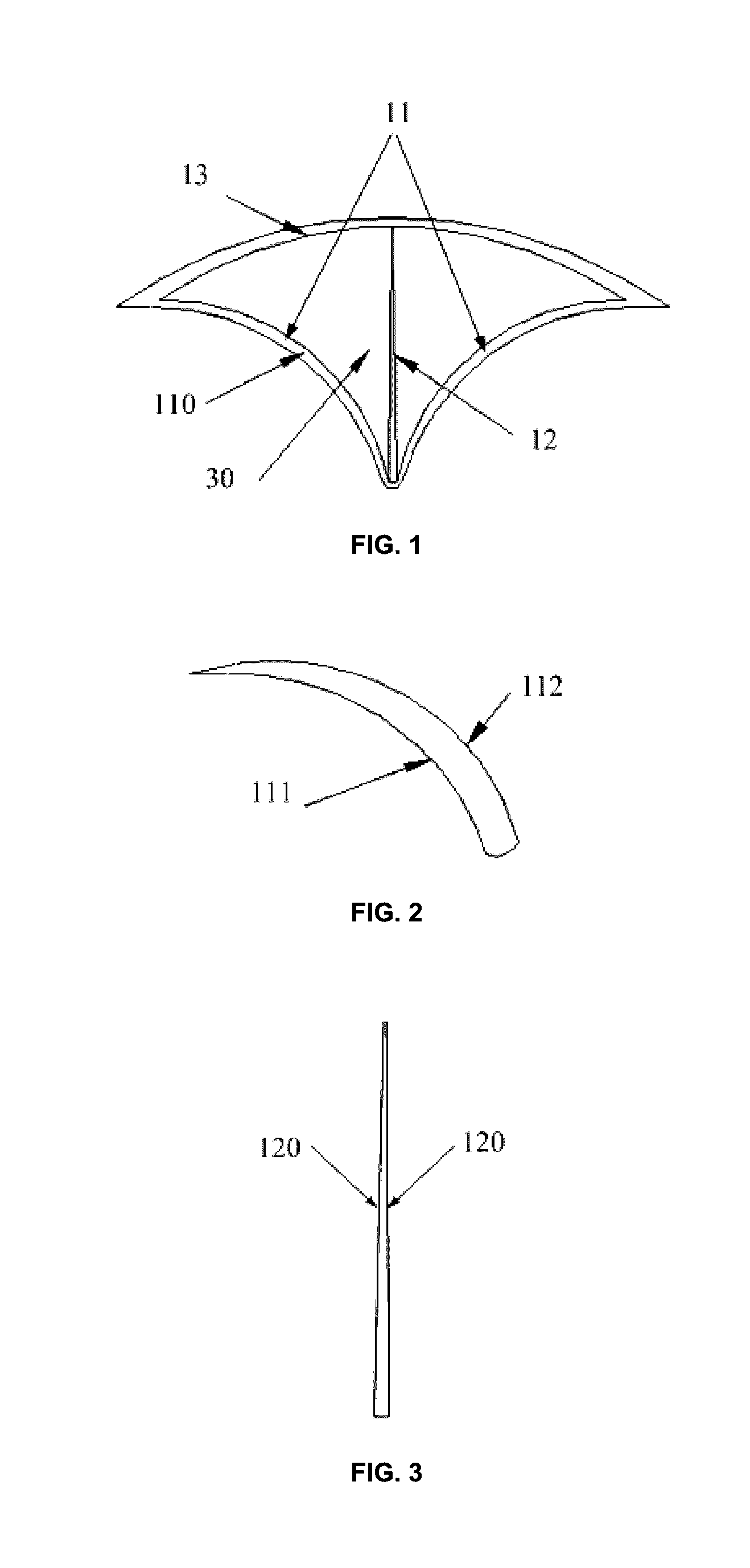
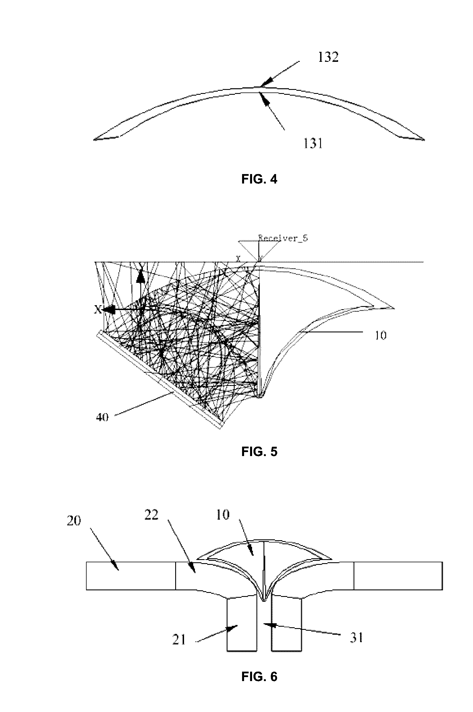
[0033]As shown in FIG. 1, the optical path adjusting unit comprises a light converging part 11, a reflective part 12 and a light scattering part 13. The light converging part 11 and the light scattering part 13 are connected together to form a hollow space, and the reflective part 12 is disposed in the hollow space and connected to the middle of the light converging part 11 and the middle of the light scattering part 13 respectively, to divide the hollow space into two parts. The light converging part 11 is used for converging the light rays incident thereon in different directions, the reflective part 12 is used for reflecting the light rays converged by the light converging part 11 to the light scattering part 13, and the light scattering part 13 is used for scattering the light rays reflected by the light reflecti...

embodiment 2

[0047]This embodiment provides a display device, which comprises the optical path adjusting unit in embodiment 1.

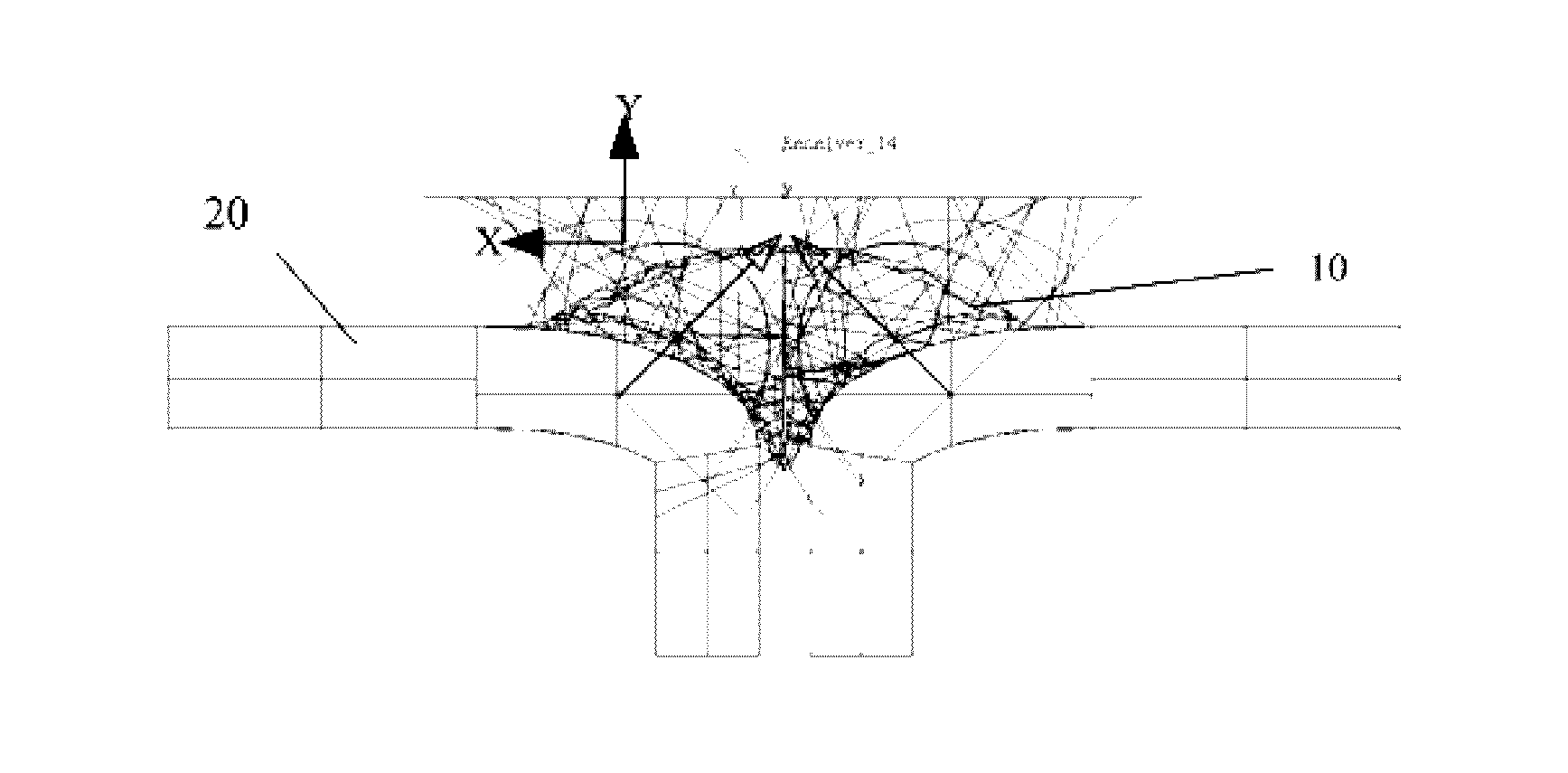
[0048]As shown in FIG. 6, the display device comprises at least two display screens 20 which can be spliced together, and there is a splicing gap 31 between the adjacent display screens 20 to be spliced, and the optical path adjusting unit 10 provided by embodiment 1 is disposed within the splicing gap 31. The outgoing light rays adjusted by the optical path adjusting unit 10 transmit in the front-facing direction, and here the term “front-facing direction” refers to the normal direction of the large-sized entire display screen spliced by a plurality of display screens.

[0049]It can be understood that the display screen 20 comprises a substrate; a black matrix (BM) and a light emitting unit (not shown in FIG. 6), which are stacked sequentially on the substrate. In this embodiment, the edge part of the display screen 20 is bended inwards (i.e., the direction opposite to the...


PUM


Abstract

The invention provides an optical path adjusting unit and a display device. The optical path adjusting unit, for adjusting light rays from different directions to transmit in approximately the same direction, comprises a light converging part, a reflective part and a light scattering part. The light converging part and the light scattering part form a hollow space, and the reflective part is disposed within the hollow space and connected to the middle of the light converging part and the middle of the light scattering part to divide the hollow space into two parts. The light converging part is used to converge the light rays from different directions; the reflective part is used to reflect the converged light rays onto the light scattering part, and the light scattering part is used to transmit the light rays reflected thereon by the reflective part out in approximately the same direction.

Description

CROSS-REFERENCES TO RELATED APPLICATIONS[0001]This patent application claims priority of Chinese Patent Application No. 201510005753.6, filed on Jan. 6, 2014, the entire content of which is incorporated by reference herein.FIELD OF THE INVENTION[0002]The present invention belongs to the technical field of display, more particularly, to an optical path adjusting unit and a display device.BACKGROUND[0003]Flat panel display technology develops rapidly in the recent decade. It has become current mainstream display technology, since both the screen size and the display quality get prominent progress. Currently, flat panel display device mainly includes Liquid Crystal Display (LCD) and Organic Light Emission Display (OLED). With the development of the Active Matrix Organic Light Emission Display (AMOLED), the application field of the flexible display screen becomes wider and wider, and the size becomes larger and larger. Moreover, for the displays with larger size, they are usually formed...

Claims


Application Information

Patent Timeline
Patent Type & Authority Applications(United States)
IPC IPC(8): F21V13/14G02B17/08G02B3/08G02B5/02G02B5/09
CPCF21V13/14G02B5/0278G02B17/086G02B3/08G02B5/0294G02B5/09G02B27/00G02F1/13336G02B27/1066G02F1/133504G02B19/009G02B17/0856H10K59/18H10K50/85G02B19/0047G02B26/0891G02B19/0023
Inventor SUN, YANLIU
Owner BOE TECH GRP CO LTD
Why Eureka
Try Eureka