Separator washing method, separator producing method, and film washing method
Inactive Publication Date: 2016-12-15
SUMITOMO CHEM CO LTD
12 Cites 1 Cited by
AI-Extracted Technical Summary
Problems solved by technology
Therefore, such a separator and a film are mo...
Benefits of technology
[0014]The separator washing method of the present invention is a method for washing a battery separator which is long and porous, and the separator washing method includes the steps of: transferring the battery separator in a longitudinal direction of the battery separator; and washing the battery separator by causing the battery separator, which is being transferred, to sequentially pass through a washing liquid in a first washing tank and a washing liquid in a second washing tank. With the configuration, it is possible to wash a porous separator whose mechanical strength is lower than a non-porous film while inhibiting a fold and a tear, and it is therefore possible to carry out sufficient washing. This makes it possible to bring about an effect of obtaining a battery separator having an air permeability higher than that of a conventional battery separator.
[0015]Moreover, the present invention includes a forming step of forming a long and porous battery separator and the steps of the separator washing method, the steps of the separator washing method being carried out after the forming step. This makes it possible to bring about an effect of producing the battery separator in which a fold and a tear are inhibited and which has an air permeability higher than that of a conventional battery separator.
[0016]The film washing method of the present invention is a...
Abstract
The present invention provides a washing method and the like suitable for a long and porous battery separator and a separator producing method including the washing method. The washing method of the present invention includes the steps of (i) transferring a separator in its longitudinal direction and (ii) washing the separator by causing the separator, which is being transferred, to sequentially pass through washing waters in washing tanks.
Application Domain
Final product manufactureSecondary cells +3
Technology Topic
Process engineeringEngineering
Image
Examples
- Experimental program(3)
Example
[0054]The following description will discuss Embodiment 1 of the present invention, with reference to FIG. 4.
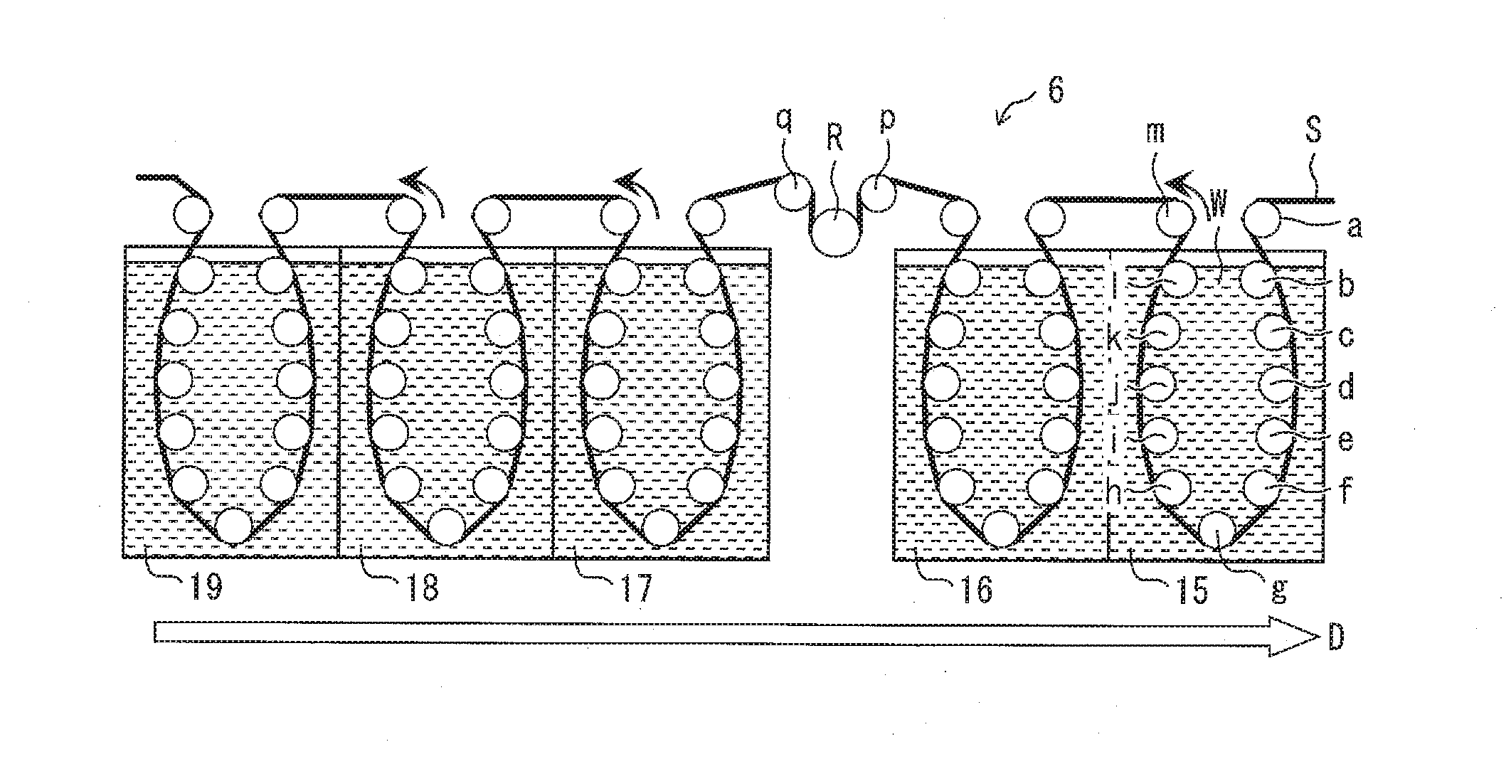
[0055]In the following embodiment, a washing method for washing a heat-resistant separator, which is a long and porous battery separator, is described. A heat-resistant layer of the heat-resistant separator is formed by applying an aramid/NMP (N-methylpyrrolidone) solution (coating solution) to a porous film. In this case, NMP (remove-target substance) which is a solvent sinks into pores of the porous film.
[0056]An air permeability of the heat-resistant separator in which NMP remains in the pores is lower than that of a heat-resistant separator in which no NMP remains in pores. As the air permeability is lower, movement of lithium ions of a lithium-ion secondary battery including the heat-resistant separator is further interfered with, and consequently output of the lithium-ion secondary battery decreases. Therefore, it is preferable to wash the heat-resistant separator so that NMP does not remain in the pores of the heat-resistant separator.
<>
(Washing Tank)
[0057]FIG. 4 is a cross-sectional view illustrating a configuration of a washing device 6 used in a washing method of the present embodiment.
[0058]As illustrated in FIG. 4, the washing device 6 includes washing tanks 15 through 19 (liquid tank). Each of the washing tanks 15 through 19 is filled with washing water W (washing liquid, liquid).
[0059]Further, the washing device 6 includes a plurality of rollers which are rotatable for transferring a heat-resistant separator S. Among the plurality of rollers, rollers a through m are rollers for transferring the heat-resistant separator S which is to be washed in the washing tank 15.
[0060]The heat-resistant separator S which has been transferred from a step (for example, coating step) which is upstream from a washing step passes through, via the rollers a through m, the washing water W (hereinafter referred to as “water”) filling the washing tank 15. The rollers a through m (transferring roller) define a transferring path of the heat-resistant separator S in the washing tank 15. In the washing tanks 16 through 19, the heat-resistant separator S is washed in a manner similar to that in the washing tank 15.
(Driving Roller)
[0061]The washing device 6 further includes a driving roller R and auxiliary rollers p and q for applying driving force to the heat-resistant separator S between washing tanks. The auxiliary rollers p and q define an angle (so-called “holding angle”) at which the heat-resistant separator S makes contact with the driving roller R. Although the driving roller R and the auxiliary rollers p and q can be provided in the washing water W, the driving roller R and the auxiliary rollers p and q are preferably provided between washing tanks as illustrated in FIG. 4, because it is not necessary to give a water-proof treatment to the rollers.
[0062]As described above, driving force for transferring the heat-resistant separator S is applied between a position of the roller a for the washing tank 15 (first washing tank) and a position of a roller (corresponding to the roller m) for the washing tank 19 (second washing tank). Here, the “position of the roller a for the washing tank 15” is a position at which the heat-resistant separator S is brought into the washing tank 15. The “position of a roller (corresponding to the roller m) for the washing tank 19” is a position at which the heat-resistant separator S is taken out from the washing tank 19.
[0063]The driving force is preferably applied to the heat-resistant separator S between (i) a position which is of a roller (corresponding to the roller 1) for the washing tank 16 (first washing tank) and is on a washing tank 17 side and (ii) a position which is of a roller (corresponding to the roller b) for the washing tank 17 (second washing tank) and is on a washing tank 16 side. Here, the “position which is of a roller (corresponding to the roller 1) for the washing tank 16 and is on a washing tank 17 side” is a position at which the heat-resistant separator S is taken out from washing water W in the washing tank 16. The “position which is of a roller (corresponding to the roller b) for the washing tank 17 and is on a washing tank 16 side” is a position at which the heat-resistant separator S is brought into the washing water W in the washing tank 17.
<>
[0064]The washing method of the present embodiment includes a step of transferring the heat-resistant separator S in a longitudinal direction of the heat-resistant separator S and a step of washing the heat-resistant separator S, which is being transferred, by causing the heat-resistant separator S to sequentially pass through washing waters W in the washing tanks 15 through 19. As such, the heat-resistant separator S is sequentially transferred from an upstream washing tank (first washing tank) to a downstream washing tank (second washing tank). Here, unless otherwise noted, the terms “upstream” and “downstream” respectively mean an upstream side and a downstream side in a transferring direction of a separator.
[0065]After washing in the washing tanks 15 through 19 has finished, the heat-resistant separator S is transferred to a step (for example, drying step) downstream from the washing step.
Effect of Present Embodiment
Washing by Diffusion
[0066]In a case where the heat-resistant separator S passes through the washing water W, NMP diffuses from the pores of the heat-resistant separator S to the water. Here, a diffusion amount of NMP becomes larger as a concentration of NMP in the washing water W is lower.
[0067]The heat-resistant separator S is washed sequentially in the washing tanks 15 through 19, and therefore a concentration of NMP in washing water W is lower in a downstream washing tank than in an upstream washing tank. That is, NMP is diffused in stages, and it is therefore possible to reliably remove NMP from the pores.
(Direction in which Washing Water Flows)
[0068]As illustrated in FIG. 4, washing water W can flow in a direction D from the downstream washing tank 19 to the upstream washing tank 15 in the separator transferring direction. From this, for example, partition walls each provided between the washing tanks 15 through 19 can have heights which become lower from the downstream side to the upstream side in the separator transferring direction. In this case, in the washing method of the present embodiment, washing water W is supplied to the downstream washing tank and the washing water W in the downstream washing tank is then supplied to an upstream washing tank, and thus the washing method further includes a step of renewing a washing liquid in each of the washing tanks. From the upstream washing tank 15, part of the washing water W flows out. With the configuration, it is possible to cause an NMP concentration in washing water W in the downstream washing tank in the separator transferring direction to be lower than an NMP concentration in washing water W in the upstream washing tank, while efficiently using the washing water W.
(Efficient Washing)
[0069]By diffusing NMP in stages, it is possible to efficiently remove NMP, as compared with washing in only one washing tank. It is therefore possible to shorten a transferring distance of the heat-resistant separator S during washing. From this, it is possible to wash the heat-resistant separator S whose mechanical strength is lower than that of a non-porous film while inhibiting a fold and a tear.
<>
(Circulation of Washing Water)
[0070]As a width of the heat-resistant separator S becomes broader, productivity increases. Therefore, the width (i.e., a width in a direction perpendicular to the sheet on which FIG. 4 is illustrated) of the heat-resistant separator S is often set to be a width similar to that of the washing tanks 15 through 19. Moreover, the width of the washing tanks 15 through 19 is designed in accordance with the width of the heat-resistant separator S.
[0071]In a case where the width of the heat-resistant separator S is broadened and a gap between an edge of the heat-resistant separator S and the washing tanks 15 through 19 becomes smaller, washing water W in each of the washing tanks 15 through 19 is to be separated into one surface side (i.e., center side of washing tank) of the heat-resistant separator S and another surface side (i.e., both end sides of washing tank (right and left sides of washing tank in FIG. 4)) of the heat-resistant separator S.
[0072]In the washing in the washing tanks 15 through 19, the washing water W is often supplied/drained by overflow between the washing tanks 15 through 19. In this case, washing water W on the one surface side of the heat-resistant separator S may be supplied/drained, whereas washing water W on the another surface side of the heat-resistant separator S may remain.
[0073]In view of this, the washing method of the present embodiment can include a step of circulating washing water W so as to facilitate interchanging of washing waters W between the one surface side and the another surface side of the heat-resistant separator S in at least one of the washing tanks 15 through 19. In this case, the washing device 6 can further include a circulating device which is provided in the at least one of the washing tanks 15 through 19 and has an inlet and an outlet for washing water W.
[0074]This makes it possible to further uniformize an NMP concentration in washing water W in one washing tank, and it is therefore possible to facilitate efficient removal of NMP.
(Washing Water)
[0075]The washing water W is not limited to water, provided that the washing water W is a washing liquid which can remove NMP from the heat-resistant separator S.
[0076]Moreover, the washing water W can contain a cleaning agent such as a surfactant, an acid (e.g., hydrochloric acid), or a base. A temperature of the washing water W is preferably 120° C. or lower. With this temperature condition, heat shrinkage of the heat-resistant separator S is less likely to occur. The temperature of the washing water W is more preferably 20° C. or higher and 100° C. or lower.
(Method for Producing Polyolefin Separator)
[0077]The above washing method for washing the heat-resistant separator S is applicable to a washing method for washing a separator (polyolefin separator) having no heat-resistant layer.
[0078]The separator is formed by stretching a film-shaped polyolefin resin composition which has been obtained by kneading high molecular weight polyolefin such as ultrahigh molecular weight polyethylene and an inorganic filler or a plasticizer. Further, the remove-target substance such as the inorganic filler or the plasticizer is washed, and thus pores of the separator are formed.
[0079]An air permeability of a separator in which the remove-target substance has not been washed and remains in pores is lower than an air permeability of a separator in which the remove-target substance does not remain in pores. As the air permeability is lower, movement of lithium ions of a lithium-ion secondary battery including a separator is further interfered with, and consequently output of the lithium-ion secondary battery decreases. Therefore, it is preferable to wash the separator so that the remove-target substance does not remain in the pores of the separator.
[0080]A washing liquid for washing a separator containing an inorganic filler is not limited, provided that the washing liquid can remove the inorganic filler from the separator. The washing liquid is preferably an aqueous solution containing an acid or a base.
[0081]A washing liquid for washing a separator containing a plasticizer is not limited, provided that the washing liquid can remove the plasticizer from the separator. The washing liquid is preferably an organic solvent such as dichloromethane.
[0082]The outline of the above is as follows: that is, the washing method for washing a film-shaped polyolefin resin composition (film) includes the steps of (i) transferring a film, which is long and is an intermediate product of the separator, in a longitudinal direction of the film and (ii) washing the film by causing the film, which is being transferred, to sequentially pass through washing liquids in the respective washing tanks 15 through 19.
[0083]As such, in FIG. 4, the heat-resistant separator S can serve as a film which is an intermediate product of a separator. Moreover, the washing water W can be an aqueous solution which contains an acid or a base.
[0084]The method for producing a polyolefin separator includes (i) a forming step of forming a film which is long, is an intermediate product of a long and porous separator, and contains polyolefin as a main component and (ii) the steps of the above film washing method which steps are carried out after the forming step.
(Method for Producing Laminated Separator)
[0085]The present invention encompasses a method for producing a heat-resistant separator S, which is a laminated separator, with use of the washing method for washing the heat-resistant separator S. Here, the heat-resistant separator S is a laminated separator including a porous film 5 (base material, first layer) and a heat-resistant layer 4 (functional layer, second layer) which is laminated on the porous film 5, as illustrated in FIG. 3. Note that the heat-resistant layer 4 is thinner than a base material layer. This producing method includes a forming step of forming a long and porous heat-resistant separator S and the steps in the above described separator washing method which steps are carried out after the forming step.
[0086]In order to laminate the heat-resistant layer 4, the “forming step” includes an applying step of applying, to the porous film 5, NMP (liquid substance) containing aramid resin (substance) for constituting the heat-resistant layer 4 and a solidifying step of solidifying the aramid resin after the applying step.
[0087]The “steps” mean the steps of (i) transferring the heat-resistant separator S in the longitudinal direction thereof and (ii) washing the heat-resistant separator S by causing the heat-resistant separator S, which is being transferred, to sequentially pass through washing waters W in the respective washing tanks 15 through 19.
[0088]From this, it is possible to produce the laminated separator which hardly contains NMP and in which a fold and a tear are inhibited. Note that the heat-resistant layer can be the early described adhesive layer.
Example
[0089]The following description will discuss Embodiment 2 of the present invention with reference to FIG. 5. For convenience of explanation, identical reference numerals are given to constituent members having functions identical with those of the constituent members described in Embodiment 1, and descriptions of such constituent members are omitted here. This applies to other embodiments described below.
<>
[0090]FIG. 5 is a cross-sectional view illustrating a peripheral configuration of a guide roller G used in a washing method of the present embodiment.
[0091]As illustrated in FIG. 5, a washing device 6 further includes a guide roller G, a Teflon bar s, and a Teflon tube t. Note that “Teflon” is a registered trademark.
[0092]The guide roller G (i) is fixed to a transferring path on which the heat-resistant separator S is transferred, (ii) does not rotate, and (iii) is provided between rollers 1 and m for a washing tank 15. An axis of the guide roller G extends in a depth direction of FIG. 5 and is in parallel with the heat-resistant separator S.
[0093]The Teflon bar s (bar-like member) extends in an axis direction of the guide roller G and is provided on a surface of the guide roller G. The Teflon bar s which is thus provided on the surface of the guide roller G is fixed by the Teflon tube t so as to be located between the guide roller G and the heat-resistant separator S.
[0094]The Teflon tube t (sheet-like member) covers (wraps) the guide roller G and the Teflon bar s so as to bind up the guide roller G and the Teflon bar s. The Teflon tube t contains synthetic resin as a main component (for example, fluorine resin).
[0095]Note that the guide roller G can be provided for any of the washing tanks 16 through 19. Moreover, the washing device 6 can include plural sets of the guide roller G, the Teflon bar s, and the Teflon tube t.
<>
[0096]The washing method of the present embodiment includes, in addition to the steps in the washing method of Embodiment 1, the step of removing washing water W from the heat-resistant separator S between an upstream washing tank and a downstream washing tank.
[0097]In a case where the heat-resistant separator S is pulled up from the water, part of washing water W in the upstream washing tank is brought to the downstream washing tank along the surface of the heat-resistant separator S. In view of this, the washing water W which is to be brought to the downstream washing tank is scraped off from the heat-resistant separator S.
[0098]The Teflon bar s which is provided on the surface of the guide roller G that is fixed serves to form a protrusion (first member) on a surface of the Teflon tube t. The protrusion is brought into contact with the heat-resistant separator S so as to softly rub the heat-resistant separator S, slides with respect to the heat-resistant separator S, and thus scrapes washing water W off from the heat-resistant separator S.
Effect of Present Embodiment
[0099]With the configuration of the present embodiment, it is possible to reduce washing water W which is to be brought from the upstream washing tank to the downstream washing tank. It is therefore possible to reliably control an NMP concentration in washing water W in the downstream washing tank to be lower than that in washing water W in the upstream washing tank. This leads to reliable removal of NMP from the pores of the heat-resistant separator S.
(Others)
[0100]The Teflon tube t does not absorb washing water W, that is, the Teflon tube t is a non-water-absorbing member. Here, if a member which slides with respect to the heat-resistant separator S has a water-absorbing property, washing water W is to be continuously absorbed by the member. In such a case, it is necessary to provide a mechanism for removing washing water W thus absorbed. For example, a sponge roller is used as the member, and a suction pump is used as the removing mechanism.
[0101]However, the sponge roller lacks durability. Moreover, the suction pump continuously consumes energy. As such, the water-absorbing member is not suitable for continuously removing water from the heat-resistant separator S.
[0102]On the other hand, according to the film producing method of the present embodiment, it is not necessary to provide such a mechanism. Therefore, it is possible to continuously remove washing water W from the heat-resistant separator S. This makes it possible to produce the heat-resistant separator S from which washing water W used in the washing treatment has been sufficiently removed.
[0103]The heat-resistant separator S and a pressing member (in the above example, the protrusion on the surface of the Teflon tube t) to be pressed against the heat-resistant separator S are configured to move at relatively different speeds. Moreover, in a case where the guide roller G is configured to rotate, it is only necessary to configure the heat-resistant separator S and the pressing member so as not to move at the same speed, regardless of a direction in which the guide roller G rotates.
[0104]In a water removing member (first member) including the guide roller G, the Teflon bar s, and the Teflon tube t, it is possible to change a shape of a part, which slides with respect to the heat-resistant separator S, by replacing the Teflon bar s with a bar having a different shape. From this, it is possible to change force which is to be applied to the heat-resistant separator S when washing water W is removed from the heat-resistant separator S.
[0105]Note that, as described below, it is possible to remove liquid from the heat-resistant separator S by causing a plate-like liquid removing member to slide with respect to the heat-resistant separator S.
[0106]In a case where the heat-resistant separator S is a polyethylene porous film which has one surface coated with a heat-resistant aramid layer, it is preferable to press the protrusion formed on the surface of the Teflon tube t against another surface of the porous film which another surface is not coated with the heat-resistant layer. That is, it is preferable that the protrusion is provided on a side opposite to the heat-resistant layer of the heat-resistant separator S, and no protrusion is provided on a heat-resistant layer side of the heat-resistant separator S. With the configuration, it is possible to remove washing water W from the heat-resistant separator S while preventing damage on the heat-resistant layer. This makes it possible to prevent detachment of the heat-resistant layer.
[0107]In other words, in a case where the heat-resistant separator S is a film having a first layer and a second layer which is thinner than the first layer (or is more likely to abrade than the first layer, or is more fragile than the first layer, or is formed later than the first layer), it is preferable to provide the Teflon tube t and the like on a first layer side of the heat-resistant separator S and preferable not to provide a member which slides with respect to the heat-resistant separator S.
Example
[0108]The following description will discuss Embodiment 3 of the present invention with reference to FIG. 6.
<>
[0109]FIG. 6 is a cross-sectional view illustrating a peripheral configuration of a roller m (transferring roller) used in a washing method of the present embodiment. As illustrated in FIG. 6, a washing device 6 further includes a scrape-off bar BL (second member).
[0110]The scrape-off bar BL is a blade for scraping off washing water W which is transferred along the roller m.
[0111]A slight gap is provided between the roller m and the scrape-off bar BL. With the configuration, the washing water W adhering to the roller m moves to the scrape-off bar BL while damage on a surface of the roller m and abrasion of the scrape-off bar BL are prevented.
<>
[0112]The washing method of the present embodiment includes, in addition to the steps in the washing method of Embodiment 1, the step of removing washing water W from the roller m for transferring the heat-resistant separator S between an upstream washing tank and a downstream washing tank.
[0113]When the heat-resistant separator S is transferred, part of washing water W is brought to the downstream washing tank along a surface of the heat-resistant separator S. Further, the part of washing water W which is brought to the downstream washing tank is transferred along the roller m. Then, the washing water W transferred along the roller m is scraped off from the roller m.
Effect of Present Embodiment
[0114]With the configuration of the present embodiment, it is possible to reduce an amount of washing water W which is brought from the upstream washing tank to the downstream washing tank. It is therefore possible to reliably control an NMP concentration in washing water W in the downstream washing tank to be lower than that in washing water W in the upstream washing tank. This leads to reliable removal of NMP from the pores of the heat-resistant separator S.
(Others)
[0115]A size of the gap provided between the roller m and the scrape-off bar BL is approximately 1 mm. Note, however, that, in a case where a larger amount of washing water W accumulates on the surface of the roller m, the above effect can be brought about with a size of the gap larger than 1 mm. The size of the gap depends on viscosity of washing water W, rotation speed of the roller m, and the like.
[0116]In a case where no gap is provided between the roller m and the scrape-off bar BL, at least one of the roller m and the scrape-off bar BL preferably contains synthetic resin as a main component. Note that it is more preferable that both the roller m and the scrape-off bar BL contain synthetic resin as a main component.
[0117]An angle of the scrape-off bar BL with respect to the roller m is 90° in the above described example. Note, however, that the angle is not limited to this and can be, for example, an acute angle.
[Variation 1]
[0118]The washing device 6 can include all the guide roller G, the Teflon bar s, the Teflon tube t (which are illustrated in FIG. 5), and the scrape-off bar BL (which is illustrated in FIG. 6).
[0119]A washing method of this variation includes, in addition to the steps in the washing method of Embodiment 1, the steps of removing washing water W from the heat-resistant separator S between the upstream washing tank and the downstream washing tank and removing washing water W from the roller m for transferring the heat-resistant separator S between the upstream washing tank and the downstream washing tank.
[0120]With the configuration, it is possible to further reduce an amount of washing water W which is brought from the upstream washing tank to the downstream washing tank. It is therefore possible to reliably control an NMP concentration in washing water W in the downstream washing tank to be lower than that in washing water W in the upstream washing tank. This leads to further reliable removal of NMP from the pores of the heat-resistant separator S.
[Variation 2]
[0121]The washing device 6 can include one washing tank. From this, the present invention encompasses the following aspect:
[0122]A separator washing method in accordance with a first aspect of the present invention is a method for washing a battery separator which is long and porous, the separator washing method including the steps of: transferring the battery separator in a longitudinal direction of the battery separator; washing the battery separator by causing the battery separator, which is being transferred, to pass through a washing liquid in a washing tank; and removing the washing liquid from the battery separator between a position at which the battery separator is brought into the washing tank and a position at which the battery separator is taken out from the washing tank.
[0123]The first aspect is an aspect in which, for example, washing water W is removed from the heat-resistant separator S (battery separator) by the guide roller G, the Teflon bar s, and the Teflon tube t as illustrated in FIG. 5, in at least one of the washing tanks 15 through 19 which are illustrated in FIG. 4. According to the first aspect, it is possible to reduce an amount of the washing liquid which is to be brought from the washing step to another step.
[0124]A separator washing method in accordance with a second aspect of the present invention is a method for washing a battery separator which is long and porous, the separator washing method including the steps of: transferring the battery separator in a longitudinal direction of the battery separator; washing the battery separator by causing the battery separator, which is being transferred, to pass through a washing liquid in a washing tank; and removing the washing liquid from a transferring roller for transferring the battery separator between a position at which the battery separator is brought into the washing tank and a position at which the battery separator is taken out from the washing tank.
[0125]The second aspect is an aspect in which, for example, washing water W is removed from the roller m (transferring roller) for transferring the heat-resistant separator S (battery separator) by the scrape-off bar BL as illustrated in FIG. 6, in at least one of the washing tanks 15 through 19 which are illustrated in FIG. 4. According to the second aspect, it is possible to reduce an amount of the washing liquid which is to be brought from the washing step to another step.
[0126]A separator washing method in accordance with a third aspect of the present invention is a method for washing a battery separator which is long and porous, the separator washing method including the steps of: transferring the battery separator in a longitudinal direction of the battery separator; washing the battery separator by causing the battery separator, which is being transferred, to pass through a washing liquid in a washing tank; and circulating the washing liquid in the washing tank so as to facilitate interchanging of washing liquids between one surface side and another surface side of the battery separator.
[0127]The third aspect is an aspect in which, for example, washing water W (washing liquid) is circulated so as to facilitate interchanging of washing waters W between the one surface side and another surface side of the heat-resistant separator S (battery separator) in at least one of the washing tanks 15 through 19 which are illustrated in FIG. 4. According to the third aspect, it is possible to further uniformize a concentration of the remove-target substance in the washing liquid in the washing tank, and it is therefore possible to facilitate efficient removal of the remove-target substance.
[0128]A separator washing method in accordance with a fourth aspect of the present invention is a method for washing a battery separator which is long and porous, the separator washing method including the steps of: transferring the battery separator in a longitudinal direction of the battery separator; and washing the battery separator by causing the battery separator, which is being transferred, to pass through a washing liquid in a washing tank, in the transferring step, driving force for transfer is applied to the battery separator between a position at which the battery separator is brought into the washing tank and a position at which the battery separator is taken out from the washing tank.
[0129]The fourth aspect is an aspect in which, for example, driving force for transfer is applied to the heat-resistant separator S (battery separator) by the driving roller R between a position at which the heat-resistant separator S is brought into the washing tank and a position at which the heat-resistant separator S is taken out from the washing tank which is at least one of the washing tanks 15 through 19 which are illustrated in FIG. 4. According to the fourth aspect, force applied to the battery separator is dispersed, as compared with a case where the battery separator is pulled merely from a location downstream from the part at which the washing step is carried out. As a result, it is possible to inhibit a problem such as cutoff of the battery separator.
[0130]Note that, in a case where a mechanism for applying driving force to the battery separator is provided in the washing liquid, the position at which the battery separator is brought into the washing tank can be a position at which the battery separator is brought into the washing water in the washing tank and the position at which the battery separator is taken out from the washing tank can be a position at which the battery separator is taken out from the washing water in the washing tank.
[0131]A separator producing method in accordance with a fifth aspect of the present invention includes: a forming step of forming a long and porous battery separator; and steps in the separator washing method in accordance with any one of the first through fourth aspects, the steps in the separator washing method being carried out after the forming step.
[0132]In the fifth aspect, for example, a heat-resistant separator S (battery separator) including a porous film 5 and a heat-resistant layer 4 laminated on the porous film 5 (see FIG. 3) are formed, and then the heat-resistant separator S is washed in at least one of the washing tanks 15 through 19 illustrated in FIG. 4. According to the fifth aspect, it is possible to produce the battery separator in which a fold and a tear are inhibited and which has an air permeability higher than that of a conventional battery separator.
[0133]According to a separator producing method in accordance with a sixth aspect of the present invention, it is possible in the fifth aspect that the battery separator is a laminated separator including a base material and a functional layer laminated on the base material; and the forming step includes (i) an applying step of applying a liquid substance containing a substance for constituting the functional layer to the base material so as to laminate the functional layer and (ii) a solidifying step of solidifying the substance after the applying step.
[0134]In the sixth aspect, for example, in order to laminate a heat-resistant layer 4 (functional layer) on a porous film 5 (base material) as illustrated in FIG. 3, NMP (liquid substance) containing aramid resin (substance) for constituting the heat-resistant layer 4 is applied to the porous film 5, the aramid resin is solidified, and the heat-resistant separator S is washed in at least one of the washing tanks 15 through 19 illustrated in FIG. 4. According to the sixth aspect, it is possible to produce the laminated separator in which a fold and a tear are inhibited and which has an air permeability higher than that of a conventional laminated separator.
[0135]A separator washing method in accordance with a seventh aspect of the present invention includes, in a film washing method for obtaining a long and porous battery separator, the steps of: transferring a film which is long and is an intermediate product of the battery separator in a longitudinal direction of the film; and washing the film by causing the film, which is being transferred, to pass through a washing liquid in a washing tank, the film containing polyolefin as a main component.
[0136]In the seventh aspect, for example, a polyolefin resin composition obtained by kneading polyolefin and an inorganic filler or a plasticizer is formed into a film, and this film is stretched to be an intermediate product of a heat-resistant separator S (battery separator). Then, the intermediate product is washed in at least one of the washing tanks 15 through 19 illustrated in FIG. 4, and thus the inorganic filler or the plasticizer is washed away. According to the seventh aspect, it is possible to obtain the polyolefin separator in which a fold and a tear are inhibited and which has an air permeability higher than that of a conventional polyolefin separator.
[0137]A separator washing method in accordance with an eighth aspect of the present invention includes: a forming step of forming a film which is long and is an intermediate product of a long and porous battery separator; a transferring step of transferring the film in a longitudinal direction of the film; and a washing step of washing the film by causing the film, which is being transferred, to pass through a washing liquid in a washing tank, the transferring step and the washing step being carried out after the forming step.
[0138]In the eighth aspect, for example, a polyolefin resin composition obtained by kneading polyolefin and an inorganic filler or a plasticizer is formed into a film, and this film is stretched to be an intermediate product of a heat-resistant separator S (battery separator). Then, the intermediate product is washed in at least one of the washing tanks 15 through 19 illustrated in FIG. 4. According to the eighth aspect, it is possible to produce the battery separator in which a fold and a tear are inhibited and which has an air permeability higher than that of a conventional battery separator.
[Variation 3]
[0139]FIG. 7 is a cross-sectional view illustrating an example in which a position of the driving roller R and positions of the auxiliary rollers p and q are changed in the washing device 6 illustrated in FIG. 4. (a) of FIG. 7 illustrates a configuration in which the driving roller R is provided at a lower position than the auxiliary rollers p and q, (b) of FIG. 7 illustrates a configuration in which the driving roller R is provided at a lower position than the auxiliary roller q and at a higher position than the auxiliary roller p, and (c) of FIG. 7 illustrates a configuration in which a plurality of removing steps are combined. In FIG. 7, the arrow V indicates a vertically downward direction.
[0140]In (a) of FIG. 7, a center Pc is a point at which the rotation axis of the driving roller R is located. A point Pa indicates a position at which the heat-resistant separator S, which has been transferred from the auxiliary roller p, starts to make contact with the driving roller R. A point Pb indicates a position at which the heat-resistant separator S starts to leave from the driving roller R so as to be transferred to the auxiliary roller q.
[0141]The driving roller R is pressed against the heat-resistant separator S so as to apply transferring force to the heat-resistant separator S. In a cross section of the driving roller R, an arc AR which is a surface of the driving roller R and is making contact with the heat-resistant separator S has a holding angle θ which is 180° or larger. Note that the holding angle θ is an angle which is formed at the center Pc (i.e., the rotation axis of the driving roller R).
[0142]As illustrated in FIG. 4, the heat-resistant separator S is pulled up from washing water W in the washing tank 16 and is then transferred to the auxiliary roller p. In this case, washing water W is adhering to the surface of the heat-resistant separator S. Part of washing water W which is adhering to a surface of the heat-resistant separator S on an auxiliary roller p side is removed when the part of washing water W makes contact with the auxiliary roller p. Meanwhile, washing water W which is adhering to a surface of the heat-resistant separator S on an opposite side of the auxiliary roller p side is transferred to the driving roller R.
[0143]Part of washing water W which is adhering to a surface of the heat-resistant separator S on a driving roller R side is removed when the part of washing water W makes contact with the driving roller R. Specifically, the part of washing water W adhering to the driving roller R is extruded in a depth direction of (a) of FIG. 7, i.e., in the rotation axis direction of the driving roller R. Then, the washing water W which has moved to an edge of the heat-resistant separator S falls in the vertically downward direction. Moreover, another part of the washing water W adhering to the driving roller R penetrates through the heat-resistant separator S and then falls in the vertically downward direction.
[0144]In this case, as the holding angle θ increases, a contact area between the driving roller R and the heat-resistant separator S increases. From this, a contact area between the driving roller R and washing water W adhering to the surface of the heat-resistant separator S also increases, and therefore an amount of washing water W to be removed from the surface of the heat-resistant separator S increases as the holding angle θ becomes larger.
[0145]The holding angle θ of the driving roller R with respect to the heat-resistant separator S is preferably 120° or larger, more preferably 150° or larger, further preferably 180° or larger.
[0146]In a case where the holding angle θ of the driving roller R with respect to the heat-resistant separator S is 120° or larger, it is possible to increase frictional force between the heat-resistant separator S and the driving roller R, and it is therefore possible to prevent slip of the heat-resistant separator S on the driving roller R. Further, the heat-resistant separator S is closely brought into contact with the driving roller R, and therefore washing water W is removed from the interface between the heat-resistant separator S and the driving roller R.
[0147]In particular, in a case where the holding angle θ is 180° or larger, the driving roller R is sandwiched by the heat-resistant separator S whose direction is changed, and this makes it possible to further increase frictional force between the heat-resistant separator S and the driving roller R. As described above, it is possible to remove washing water W from the heat-resistant separator S while applying transferring force to the heat-resistant separator S.
[0148]In a case where the heat-resistant separator S has been prepared by coating one surface of a polyethylene porous film with a heat-resistant aramid layer, it is preferable that the driving roller R is provided on a side of the heat-resistant separator S opposite to the heat-resistant layer and the driving roller R is not provided on a heat-resistant layer side of the heat-resistant separator S. With the arrangement, it is possible to remove washing water W from the heat-resistant separator S without causing damage on the heat-resistant layer.
[0149]As illustrated in (b) of FIG. 7, the driving roller R can be provided at a lower position than the auxiliary roller q and at a higher position than the auxiliary roller p. In this case also, it is possible to remove washing water W from the heat-resistant separator S while applying transferring force to the heat-resistant separator S. As such, a positional relation of the driving roller R and the auxiliary rollers p and q is not limited to the arrangements illustrated in (a) and (b) of FIG. 7.
(Combination of Removing Steps)
[0150]As illustrated in (c) of FIG. 7, it is possible to combine at least two of the first removing step illustrated in FIG. 5, the second removing step illustrated in FIG. 6, and the driving step illustrated in (a) of FIG. 7.
[0151]The first removing step is a step of removing washing water W from the heat-resistant separator S by sliding the water removing member (first member), which includes the guide roller G, the Teflon bar s, and the Teflon tube t, with respect to the heat-resistant separator S which has been taken out from the washing water W.
[0152]The second removing step is a step of removing washing water W from the roller m (transferring roller) which is provided for transferring the heat-resistant separator S, which has been taken out from the washing water W in the washing tank 15, to the washing step of washing the heat-resistant separator S by causing the heat-resistant separator S to pass through washing water W in the washing tank 16.
[0153]The driving step is a step of pressing the driving roller R against the heat-resistant separator S which has been taken out from washing water W after the washing step of washing the heat-resistant separator S by causing the heat-resistant separator S to pass through the washing water W in the washing tank 16 and before a drying treatment or another washing treatment. In the driving step, the holding angle θ of the driving roller R with respect to the heat-resistant separator S is 180° or larger.
(Position at which Removing Step is Carried Out)
[0154]As illustrated in FIG. 4, the heat-resistant separator S which has been subjected to the washing treatment in the washing tank 16 is transferred to the washing tank 17. In this case, the first removing step, the second removing step, and the driving step are carried out on a transferring path which is from a position at which the heat-resistant separator S is taken out from the washing water W in the washing tank 16 to a position at which the heat-resistant separator S is brought into washing water W in the washing tank 17.
[0155]The first removing step, the second removing step, and the driving step can be carried out for each of the washing tanks 15 and 17 through 19. In particular, in a case where the first removing step, the second removing step, and the driving step are carried out for the washing tank 19, the first removing step, the second removing step, and the driving step are carried out on a transferring path which is from a position at which the heat-resistant separator S is taken out from the washing water W in the washing tank 19 to a position from which the heat-resistant separator S is transferred to a treatment (for example, drying treatment) downstream from the washing treatment. That is, the first removing step, the second removing step, and the driving step are carried out before another treatment for processing (i.e., making a change to) the heat-resistant separator S.
PUM


Description & Claims & Application Information
We can also present the details of the Description, Claims and Application information to help users get a comprehensive understanding of the technical details of the patent, such as background art, summary of invention, brief description of drawings, description of embodiments, and other original content. On the other hand, users can also determine the specific scope of protection of the technology through the list of claims; as well as understand the changes in the life cycle of the technology with the presentation of the patent timeline. Login to view more.
Similar technology patents
Food packaging articles
ActiveUS20200063367A1high air permeabilityhigh thickness
Owner:EASTMAN CHEM CO
High-ventilated degradable medicine-carrying skin wound dressing as well as preparation method and device thereof
Owner:PKU HKUST SHENZHEN HONGKONG INSTITUTION +1
Bio-based all-fiber self-powered multifunctional electronic skin and preparation method thereof
PendingCN114190923AGood humidity and temperature sensitivity and detection rangehigh air permeability
Owner:SHAANXI UNIV OF SCI & TECH
Method for manufacturing ultraviolet-proof polyester knitted fabric
InactiveCN103643524AHigh air permeabilityImprove the protection factor
Owner:CHANGSHU XINLEI KNITTING
Low resilience flexible polyurethane foam and process for its production
Owner:ASAHI GLASS CO LTD
Classification and recommendation of technical efficacy words
- high air permeability
Food packaging articles
ActiveUS20200063367A1high air permeabilityhigh thickness
Owner:EASTMAN CHEM CO
High-ventilated degradable medicine-carrying skin wound dressing as well as preparation method and device thereof
Owner:PKU HKUST SHENZHEN HONGKONG INSTITUTION +1
Method for manufacturing ultraviolet-proof polyester knitted fabric
InactiveCN103643524AHigh air permeabilityImprove the protection factor
Owner:CHANGSHU XINLEI KNITTING
Bio-based all-fiber self-powered multifunctional electronic skin and preparation method thereof
PendingCN114190923AGood humidity and temperature sensitivity and detection rangehigh air permeability
Owner:SHAANXI UNIV OF SCI & TECH
Low resilience flexible polyurethane foam and process for its production
Owner:ASAHI GLASS CO LTD