Eureka AIR delivers breakthrough ideas for toughest innovation challenges, trusted by R&D personnel around the world.

Power modules and pin thereof

Active Publication Date: 2016-12-15
DELTA ELECTRONICS INC
View PDF17 Cites 6 Cited by
  • Summary
  • Abstract
  • Description
  • Claims
  • Application Information

AI Technical Summary

Benefits of technology

The present invention provides a pin structure that can be used for connections between vertical modules, such as power or control modules, and external system boards in a stacked structure. This design helps to reduce the size of the external board and increase power density.

Problems solved by technology

Since discrete devices are large in number, it is tedious to install these auxiliary parts.
Besides, due to the purpose of standardization for the discrete devices, utilization ratio of internal spaces is extremely low.
However, they suffer from a drawback that they occupy a large area of the external system board.
1) The process for producing pins and inserting pins into the substrate has a low efficiency and a high cost.
2) Pin connections between the upper and lower substrates occupy additional area on the substrate.
3) It is difficult to make a plastic package of the structure as a whole and to dissipate heat from the structure, and the structure has a poor structural reliability.

Method used

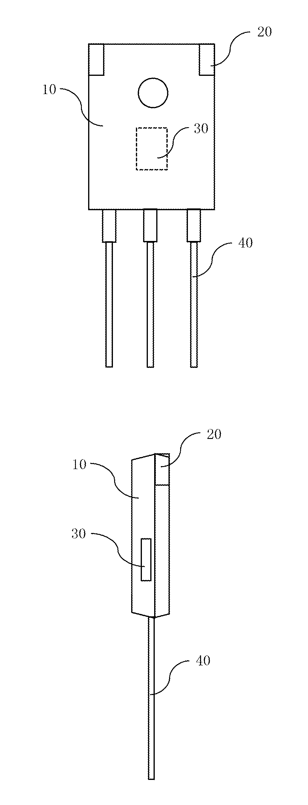
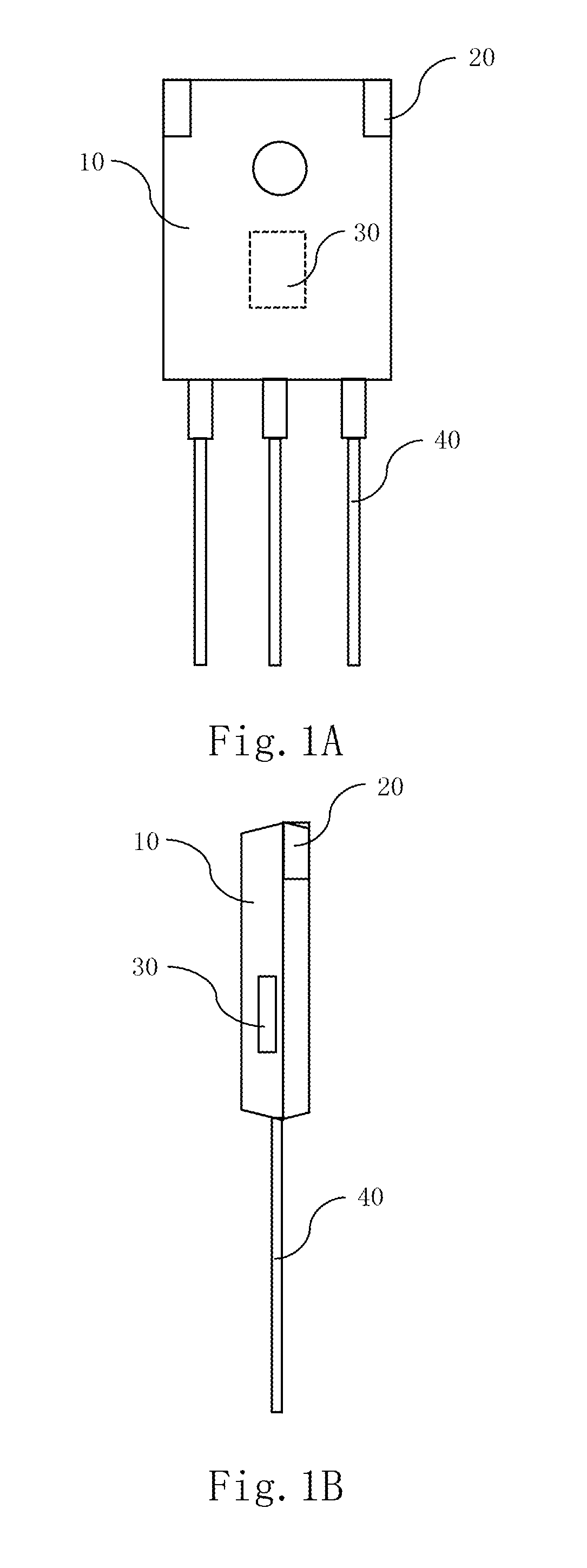
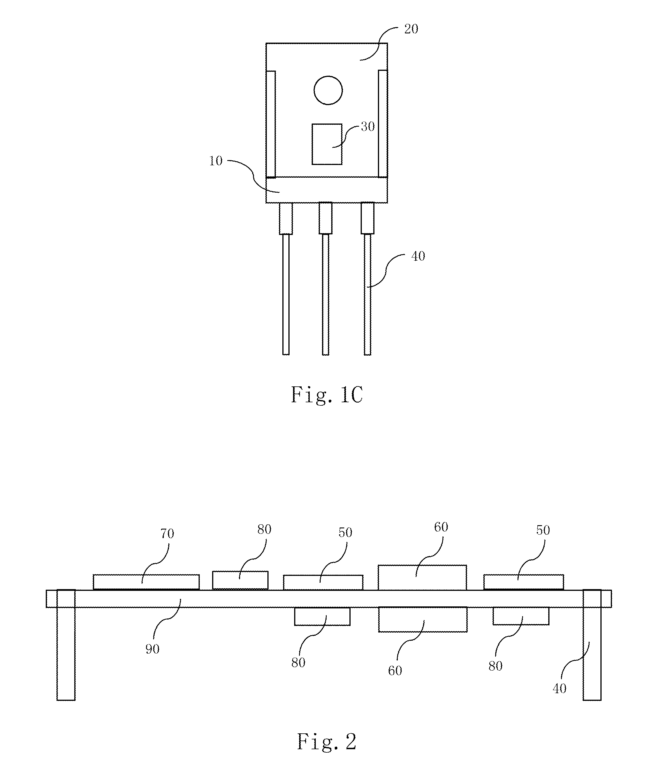

Image

  • Power modules and pin thereof
  • Power modules and pin thereof
  • Power modules and pin thereof

Examples


Embodiment Construction

[0050]The principles of structures and operations of the present invention will be described in details hereinafter by reference to the accompanying drawings.

[0051]Reference is made to FIG. 6-FIG. 9B, FIG. 6 is a schematic view of a power module in a first embodiment of the present invention, FIG. 7 is a schematic view of a power module in a second embodiment of the present invention, FIG. 8 is a schematic view of a power module in a third embodiment of the present invention, FIG. 9A is a schematic view of a power module in a fourth embodiment of the present invention, and FIG. 9B is a side view of FIG. 9A. In the present invention, a power module includes at least three circuit modules which are vertically stacked and connected. As shown in FIG. 6, the at least three circuit modules include a first circuit module 1, a second circuit module 2, and a third circuit module (not shown) in which at least one is a power circuit module, and these circuit modules are electrically connected ...


PUM


Abstract

A power module with vertically stacked structure and a pin thereof are disclosed. The power module comprises at least three circuit modules. The at least three circuit modules are a first circuit module, a second circuit module and a third circuit module. The pin is led from the first circuit module. The pin comprises: a main body, a first connection surface and a second connection surface. An upper part of the main body is electrically connected with the first circuit module. The first connection surface is provided at a middle part of the main body and electrically connected with the second circuit module. The second connection surface is provided at a terminal of the main body and electrically connected with the third circuit module.

Description

CROSS-REFERENCE TO RELATED APPLICATIONS[0001]This non-provisional application claims priority under 35 U.S.C. §119(a) on Patent Application No. 201510312461.7 filed in P.R. China on Jun. 9, 2015, the entire contents of which are hereby incorporated by reference.[0002]Some references, if any, which may include patents, patent applications and various publications, may be cited and discussed in the description of this invention. The citation and / or discussion of such references, if any, is provided merely to clarify the description of the present invention and is not an admission that any such reference is “prior art” to the invention described herein. All references listed, cited and / or discussed in this specification are incorporated herein by reference in their entireties and to the same extent as if each reference was individually incorporated by reference.FIELD OF THE INVENTION[0003]The present invention relates to a connection component of a semiconductor device, and particularl...

Claims


Application Information

Patent Timeline
IPC IPC(8): H05K7/02H02M7/04H02M7/44H01R12/58H02M1/42H05K7/20H02M7/00H01R12/52H02M3/04H02M5/04
CPCH05K7/023H02M3/04H02M7/04H02M7/44H01R12/585H02M1/42H05K7/209H02M7/003H01R12/52H02M5/04
Inventor LIANG, LEHONG, SHOUYUZHAO, ZHENQING
Owner DELTA ELECTRONICS INC
Why Eureka
Eureka Blog
Learn More