Open-pore balloon catheter

a balloon catheter and open-pore technology, applied in the field of catheters, can solve the problem of affecting the and the wall portion facing toward the body is more difficult to press against the tissue, and achieves the effect of fast and reliable drainage of body fluids

Inactive Publication Date: 2016-12-22
LOHMANN & RAUSCHER
View PDF9 Cites 52 Cited by
  • Summary
  • Abstract
  • Description
  • Claims
  • Application Information

AI Technical Summary

Benefits of technology

[0008]In view of the described problems, it is the object of the present invention to refine a catheter, anchored in the body by means of an

Problems solved by technology

Because of its open-pore nature, it becomes more difficult for the wall por

Method used


Image

  • Open-pore balloon catheter
  • Open-pore balloon catheter
  • Open-pore balloon catheter

Examples


first embodiment

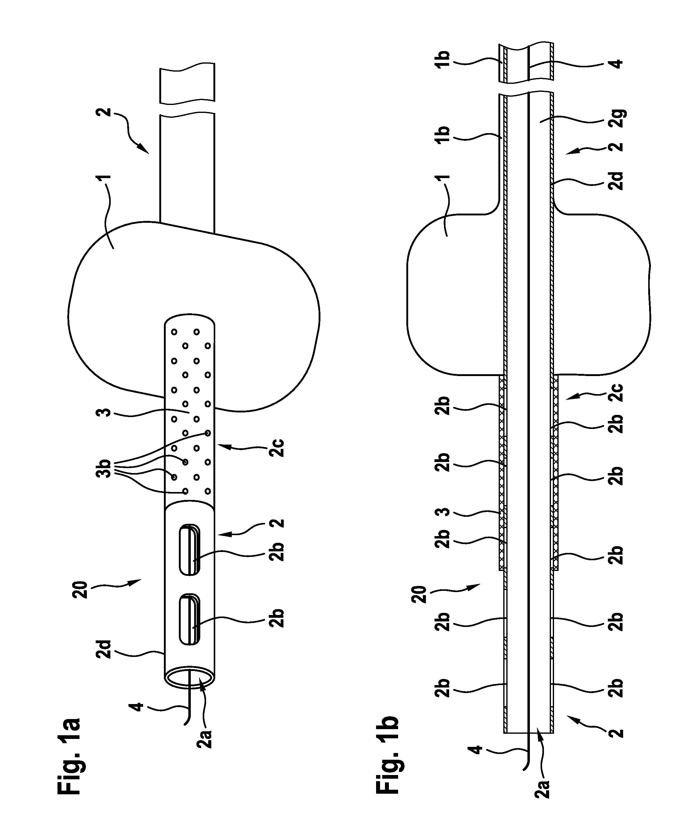
[0102]In FIGS. 1a and 1b, a catheter 20 of the invention, in the form of a balloon drain, is shown in a side view (FIG. 1a) and in a longitudinal sectional view (FIG. 1b).

[0103]The balloon drain is shown with an expansion element in the form of an expanding balloon 1, the cross section of which is enlarged in order to firmly hold the distal end of the catheter in a body cavity. The balloon 1 is seated annularly on a fluid-carrying element 2, which has a drainage tube 2d with an inner lumen 2g and extends from the proximal end, which emerges from the body and is shown on the right in the drawings, in the direction of the distal end of the catheter, which is to be located in the interior of the body and is shown on the left in the drawings. The drawings essentially show only the distal end portion of the catheter; the length of the drainage tube 2d is shown shorter than it actually is.

[0104]Distally of the balloon 1, the drainage tube 2d is circularly sheathed by a wall portion 2c of ...

second embodiment

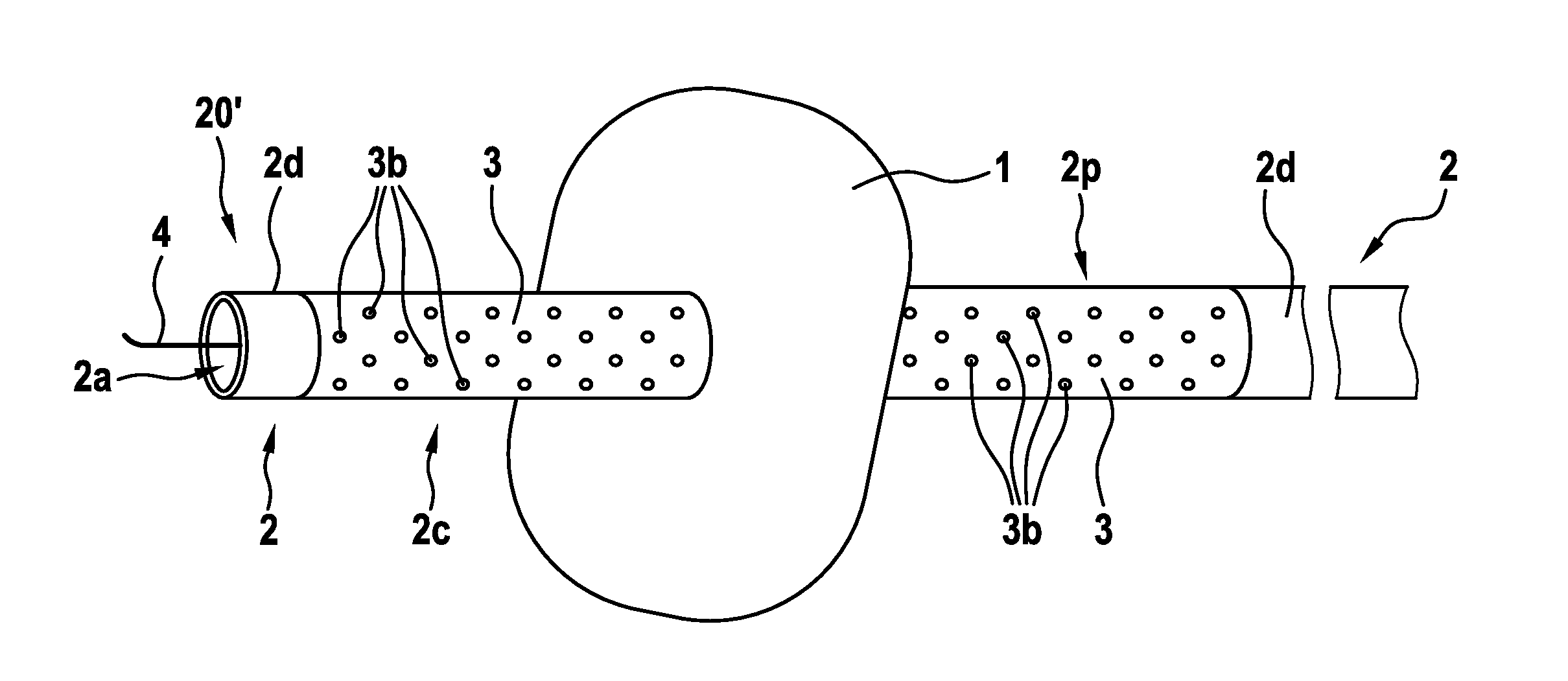
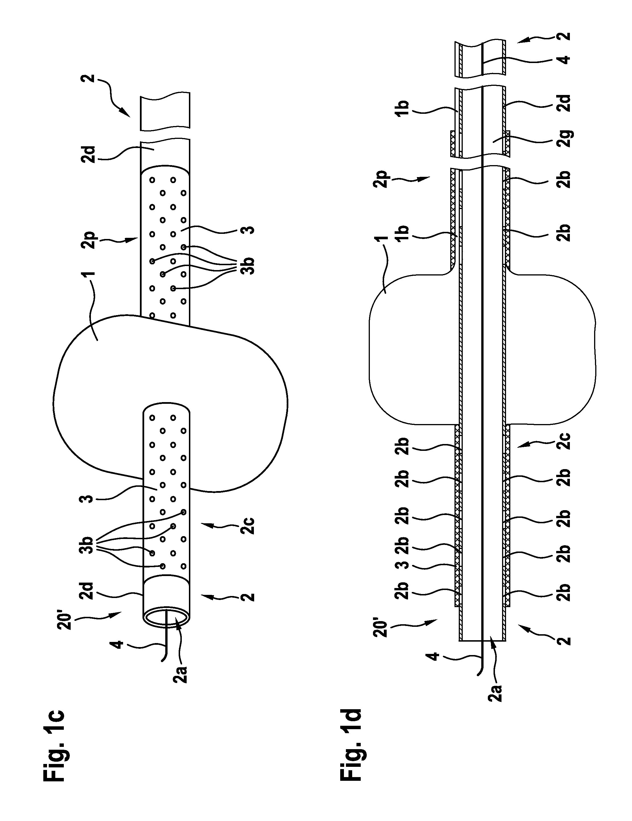
[0107]In FIGS. 1c and 1d, a catheter 20′ of the invention in the form of a balloon drain is shown in a side view (FIG. 1c) and in a longitudinal sectional view (FIG. 1d).

[0108]The balloon drain is shown with an expansion element in the form of an expanded balloon 1, whose cross section is enlarged in order to firmly hold the distal catheter end in a body cavity. The balloon 1 is seated annularly on a fluid-carrying element 2, which has a drainage tube 2d with an inner lumen 2g and extends from the proximal end of the catheter, which protrudes from the body and is shown on the right in the drawing, in the direction of the distal end, which is to be located in the interior of the body and is shown on the left in the drawings. The drawings essentially show only the distal end portion of the catheter; the length of the drainage tube 2d is shown shorter than it actually is.

[0109]Distally of the balloon 1, the drainage tube 2d is sheathed circularly by a first wall portion 2c of an open-p...

third embodiment

[0112]In FIGS. 1e and 1f, a catheter 20″of the invention is shown in the form of a balloon drain, in a side view (FIG. 1e) and in a longitudinal sectional view (FIG. 1f).

[0113]The balloon drain is shown with an expansion element in the form of an expanded balloon 1, whose cross section is enlarged in order to firmly hold the distal catheter end in a body cavity. The balloon 1 is seated annularly on a fluid-carrying element 2, which has a drainage tube 2d with an inner lumen 2g that extends from the proximal end of the catheter that protrudes from the body and is shown on the right in the drawing, in the direction of the distal end, to be located in the interior of the body and shown on the left in the drawings. The drawings essentially show only the distal end portion of the catheter; the length of the drainage tube is shown shorter than it actually is.

[0114]Proximally of the balloon 1, the drainage tube 2d is circularly sheathed by a wall portion 2p of an open-pore material 3, in t...


PUM


Abstract

The invention relates to a catheter, in particular a balloon catheter, having a fluid-carrying element, such as a drainage tube, with an inner lumen for carrying away body fluid, and having an expansion element, such as a balloon of variable cross section, for fixing the catheter in a body cavity. The fluid-carrying element has a wall portion of an open-pore material, which is in fluidic communication with the inner lumen and through which the body fluid can be aspirated into the inner lumen by applying a negative pressure to a proximal end of the fluid-carrying element. The invention furthermore relates to a catheter system having a catheter of the invention and to a vacuum-generating system connected to the catheter.

Description

CROSS-REFERENCE TO RELATED APPLICATIONS[0001]This application is based on and claims priority to European Patent Application Serial No. 15 001 736.6, filed on Jun. 11, 2015, which is incorporated herein by reference in its entirety.STATEMENT REGARDING FEDERALLY SPONSORED RESEARCH OR DEVELOPMENT[0002]Not applicable.BACKGROUND OF THE INVENTION[0003]The invention relates to a catheter, in particular a balloon catheter, having a fluid-carrying element with an inner lumen for carrying away body fluids and / or gases from the interior of the body, and having an expansion element, such as a balloon, of variable cross section for keeping or fixing the catheter portion in a body cavity. The fluid-carrying element can have a tube element, such as a drainage tube, and the expansion element can have a balloon.[0004]Such catheters are used among other ways as bladder catheters, which are inserted into the urinary bladder either via the urethra (transurethrally) or the abdominal wall (suprapubicall...

Claims


Application Information

Patent Timeline
IPC IPC(8): A61M3/02A61M25/10A61M31/00A61M1/00A61B17/34A61M25/09
CPCA61M3/0295A61M2025/09175A61B17/3415A61M25/09A61M31/00A61M1/0084A61M3/0283A61M1/005A61M25/1002A61B2017/3413A61M2210/101A61M2210/1053A61M2210/1085A61M2205/18A61M2025/105A61M2025/1088A61B17/3403A61M25/0017A61M25/10A61M25/1018A61M25/1025A61M27/00A61M25/0068A61M25/0067A61M25/09016A61M25/09025A61M25/1011A61M2025/091A61M25/10185A61M25/10186A61M1/74A61M1/782A61M1/85A61M1/772A61M1/60A61M1/84A61M3/0279A61M25/0043A61M29/00A61M25/007A61M25/04A61M2025/0095A61M2025/1086A61M2202/0496A61F5/4404A61M2025/0078
Inventor LOSKE, GUNNAR
Owner LOHMANN & RAUSCHER
Why Eureka
Try Eureka