Vehicle lamp

Active Publication Date: 2016-12-22
KOITO MFG CO LTD
View PDF6 Cites 10 Cited by
  • Summary
  • Abstract
  • Description
  • Claims
  • Application Information

AI Technical Summary

Benefits of technology

[0028]According to one or more embodiments of the invention, in a vehicle lamp that is equipped with a light guide body having first and second rod-like light guide

Problems solved by technology

However, where as in the light guide body disclosed in Patent document 1 the second rod-like light guide portion branches off from the circumferential surface of the first rod-like light guide po

Method used


Image

  • Vehicle lamp
  • Vehicle lamp
  • Vehicle lamp

Examples


Embodiment Construction

[0038]Embodiments of the present invention will be hereinafter described with reference to the drawings. In embodiments of the invention, numerous specific details are set forth in order to provide a more thorough understanding of the invention. However, it will be apparent to one of ordinary skill in the art that the invention may be practiced without these specific details. In other instances, well-known features have not been described in detail to avoid obscuring the invention.

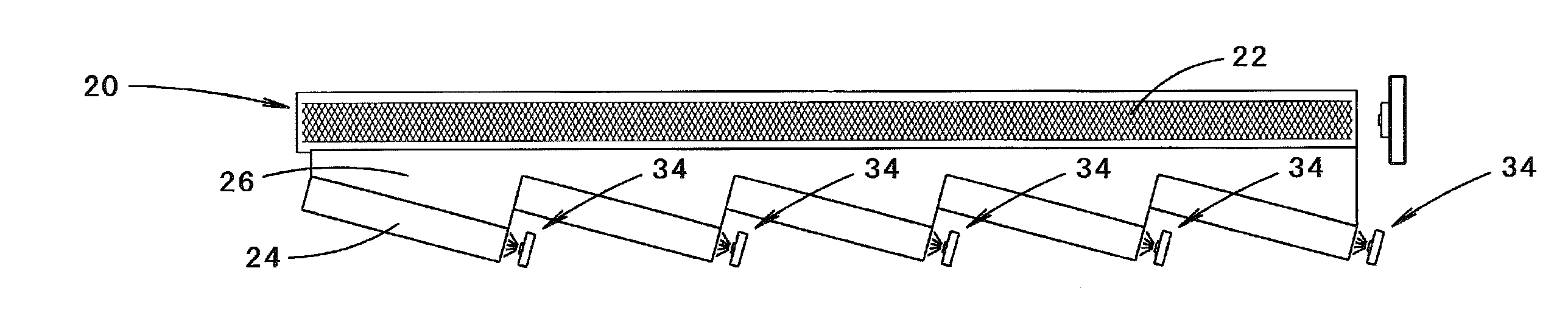
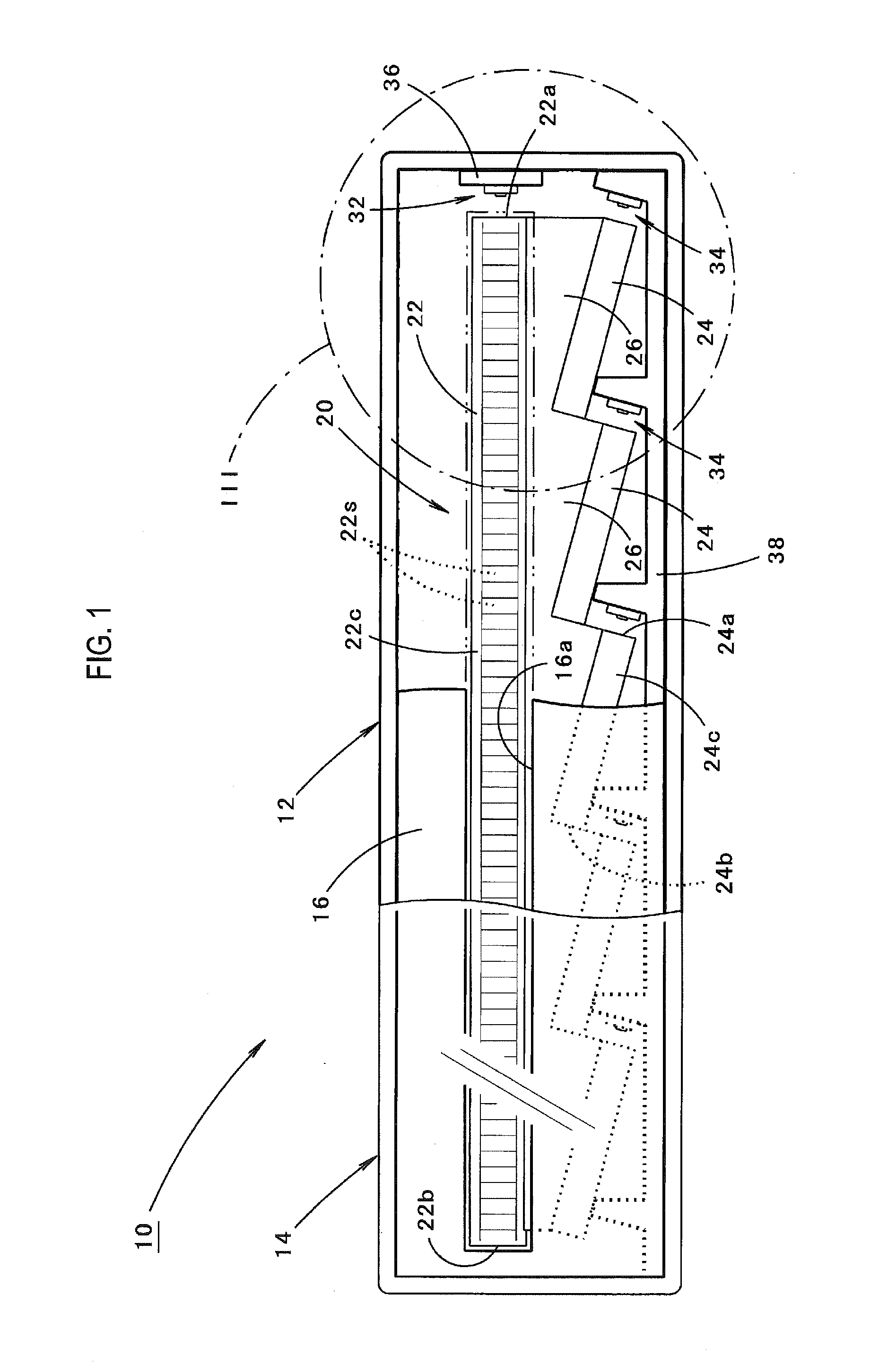
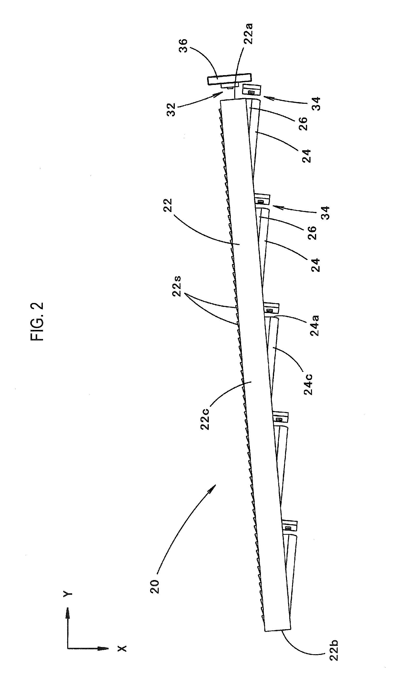
[0039]FIG. 1 is a front view of a vehicle lamp 10 according to one or more embodiments of the invention. FIG. 2 is a plan view of major constituent elements of the vehicle lamp 10.

[0040]As shown in FIGS. 1 and 2, the vehicle lamp 10 according to one or more embodiments of the present invention is a combination lamp disposed at a front-left end position of a vehicle and functions as a clearance lamp and a front turn signal lamp.

[0041]The vehicle lamp 10 is equipped with a lamp body 12 and a seethrough trans...


PUM


Abstract

A light guide body includes a first rod-like light guide portion and second rod-like light guide portions which are spaced from the first rod-like light guide portion in the vertical direction and plate-like light guide portions which are disposed so as to link their circumferential surfaces. Light that reaches the first rod-like light guide portion via the plate-like light guide portions after being emitted from light sources and entering the second rod-like light guide portions is emitted forward of the lamp from the circumferential surface of the first rod-like light guide portion.

Description

CROSS-REFERENCE TO RELATED APPLICATIONS[0001]The present application is a national stage application of PCT / JP2014 / 066619, and claims priority from Japanese Patent Application No. 2013-138633 filed on Jul. 2, 2013, the contents of which are incorporated herein in their entirety.BACKGROUND[0002]Technical Field[0003]The present invention relates to a vehicle lamp having a light guide body.[0004]Related Art[0005]Conventionally, a vehicle lamp configuration is known that includes a light guide body that receives light emitted from a light source and emits guided light forward of the lamp.[0006]In this configuration, in the case where the light guide body is a rod-like one, in general, light emitted from the light source is caused to enter one end face or both end faces of the rod-like light guide body.[0007]Patent document 1 discloses a light guide body of a vehicle lamp having a configuration that includes a first rod-like light guide portion and a second rod-like light guide portion t...

Claims


Application Information

Patent Timeline
IPC IPC(8): F21S8/10
CPCF21S48/225F21S48/2237F21S48/2243F21S48/2212F21S48/2268F21S48/215F21S48/2281B60Q1/2607B60Q1/28B60Q1/34G02B6/0038G02B6/0075B60Q2400/20F21S41/29F21S43/14F21S43/26F21S43/237F21S43/239F21S43/245F21S43/249F21S43/241B60Q1/381F21S43/247
Inventor NAKADA, ASAMI
Owner KOITO MFG CO LTD
Why Eureka
Try Eureka