
Surface light source module

a light source module and surface technology, applied in the field of light sources, can solve the problems of reducing the performance of total internal reflection and reducing the light utilization efficiency, and achieve the effect of improving light utilization efficiency

Inactive Publication Date: 2016-12-22
YOUNG LIGHTING TECHNOLOGY INC
View PDF4 Cites 8 Cited by
  • Summary
  • Abstract
  • Description
  • Claims
  • Application Information

AI Technical Summary

Benefits of technology

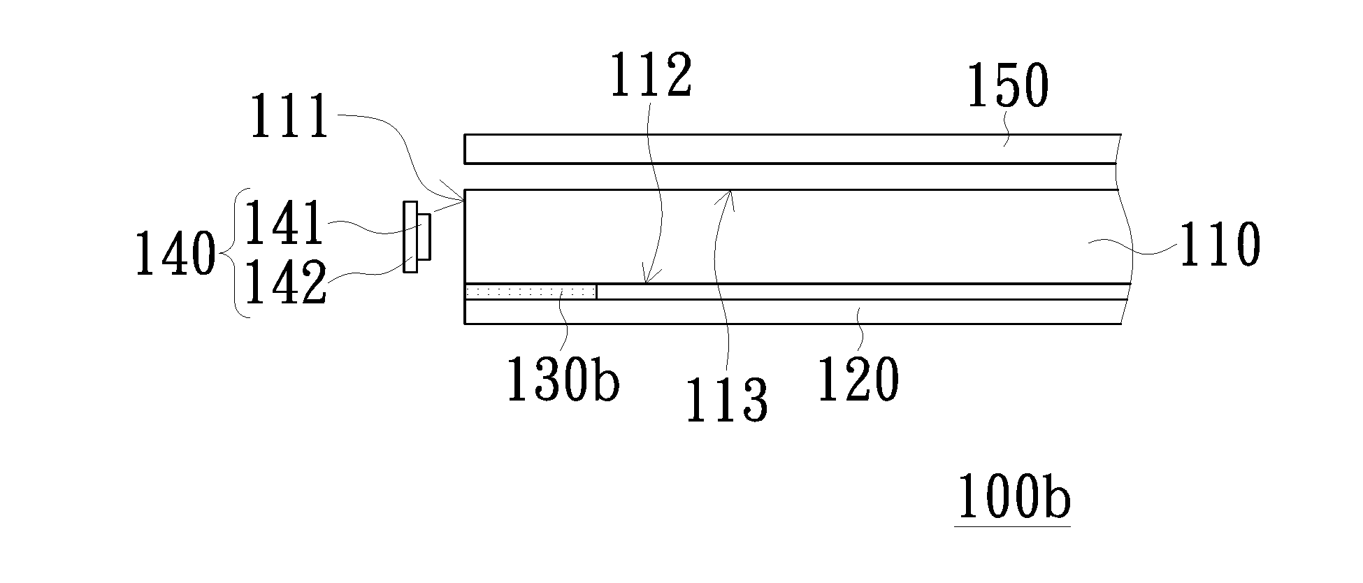
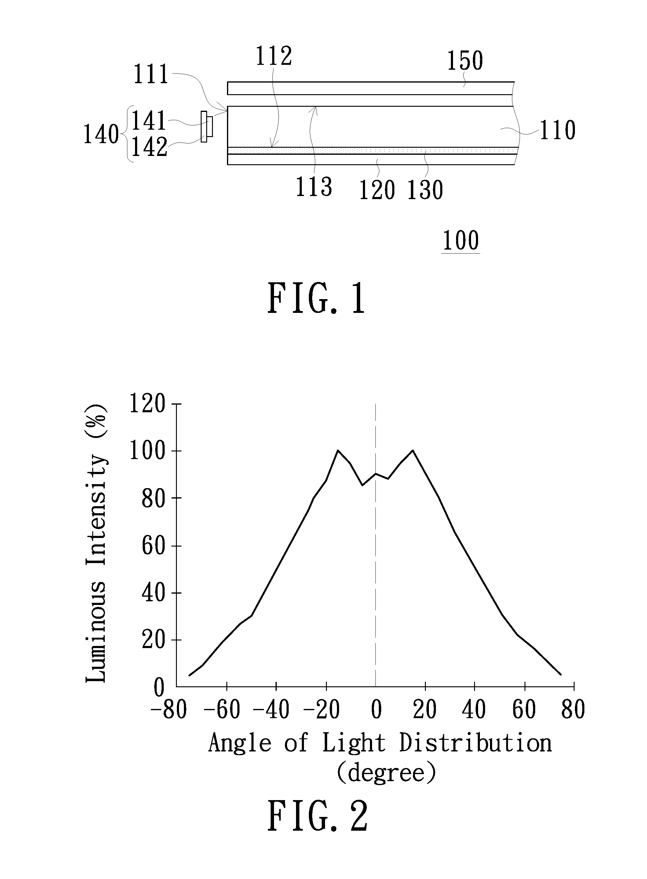
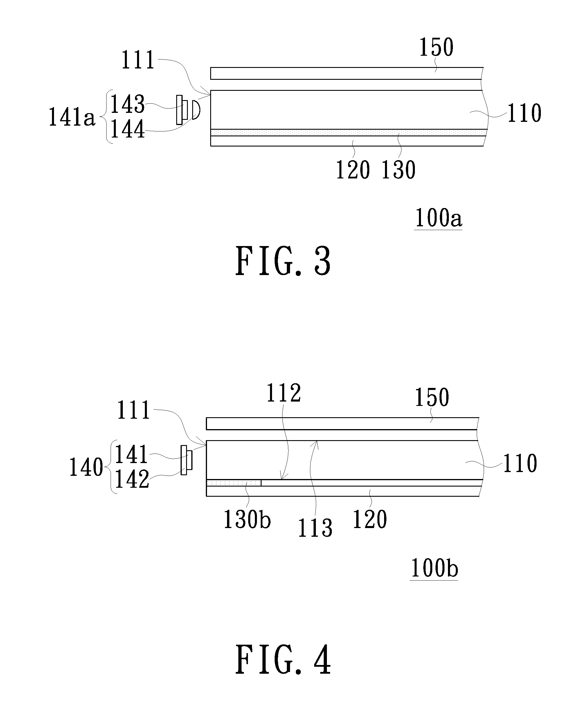
The invention provides a surface light source module that improves light utilization efficiency and is thinner. This is achieved by configuring the ratio of refractive indices between adhesive and light guiding plate and utilizing light emitting elements with specific distribution curve of luminous intensity. Additionally, the back plate of the surface light source module includes a reflective surface, which eliminates the need for a reflective sheet.

Problems solved by technology

However, the presence of adhesive has been known to reduce the performance of total internal reflection at the bottom surface of the light guiding plate, thus leading to reduction in light utilization efficiency.

Method used


Image

  • Surface light source module
  • Surface light source module
  • Surface light source module

Examples


Embodiment Construction

[0019]In the following detailed description of the preferred embodiments, reference is made to the accompanying drawings which form a part hereof, and in which is shown by way of illustration specific embodiments in which the invention may be practiced. In this regard, directional terminology, such as “top”, “bottom”, “front”, “back”, etc., is used with reference to the orientation of the Figure(s) being described. The components of the invention can be positioned in a number of different orientations. As such, the directional terminology is used for purposes of illustration and is in no way limiting. On the other hand, the drawings are only schematic and the sizes of components may be exaggerated for clarity. It is to be understood that other embodiments may be utilized and structural changes may be made without departing from the scope of the invention. Also, it is to be understood that the phraseology and terminology used herein are for the purpose of description and should not b...


PUM


Abstract

A surface light source module includes a light guiding plate having a light incidence surface and a bottom surface adjacent to the light incidence surface; a reflective sheet disposed on the bottom surface; an adhesive adhered between the bottom surface and the reflective sheet; and a light emitting assembly disposed alongside of the light incident surface. The refractive indices of the adhesive and the light guiding plate are N1 and N2, wherein 63%≦N1 / N2≦95%. The light emitting assembly includes a plurality of light emitting elements, of which the distribution curve of luminous intensity satisfies the following conditions: (1) an absolute value of distribution angle at 50% of luminous intensity is smaller than or equal to 55°; and (2) a sum of luminous energy at the absolute value of distribution angle of greater than 70° is smaller than or equal to 10% of a total lumen of the light emitting element.

Description

FIELD OF THE INVENTION[0001]The invention relates to a light source, and more particularly to a surface light source module.BACKGROUND OF THE INVENTION[0002]A liquid crystal display (LCD) device includes a LCD panel and a backlight module. As the LCD panel is not self-illuminating, the backlight module is adopted to provide light source for displaying image. Consequently, the quality of light source provided by the backlight module has direct influence on the quality of displayed image.[0003]The backlight modules can be divided into a direct-type backlight module and an edge-type backlight module. The edge-type backlight module is thinner than the direct-type backlight module, and has thus been used extensively in thin LCD devices. In a typical edge-type backlight module, light beams entering a light guiding plate from a light incidence surface of the light guiding plate would perform total internal reflection. Properly microstructures are disposed to destroy the total internal refl...

Claims


Application Information

Patent Timeline
Patent Type & Authority Applications(United States)
IPC IPC(8): F21V8/00
CPCG02B6/005G02B6/0068G02B6/0055G02B6/0066G02B6/0073G02B6/0088G02F1/133603G02F1/133605G02F1/133606G02F1/133615G02F1/133607
Inventor CHANG, JUNG-WEITSAI, YI-YULEE, HSIN-HUNGYANG, CHIAO-CHIH
Owner YOUNG LIGHTING TECHNOLOGY INC
Learn More