Projection system and projector

Active Publication Date: 2016-12-22
SEIKO EPSON CORP
View PDF1 Cites 4 Cited by
  • Summary
  • Abstract
  • Description
  • Claims
  • Application Information

AI Technical Summary

Benefits of technology

[0009]An advantage of some aspects of the invention is to provide a projection system used in a projector and r

Problems solved by technology

However, to perform the back focus adjustment by rotation of the fixed lens section as described above, when the rotating acti

Method used


Image

  • Projection system and projector
  • Projection system and projector
  • Projection system and projector

Examples


example

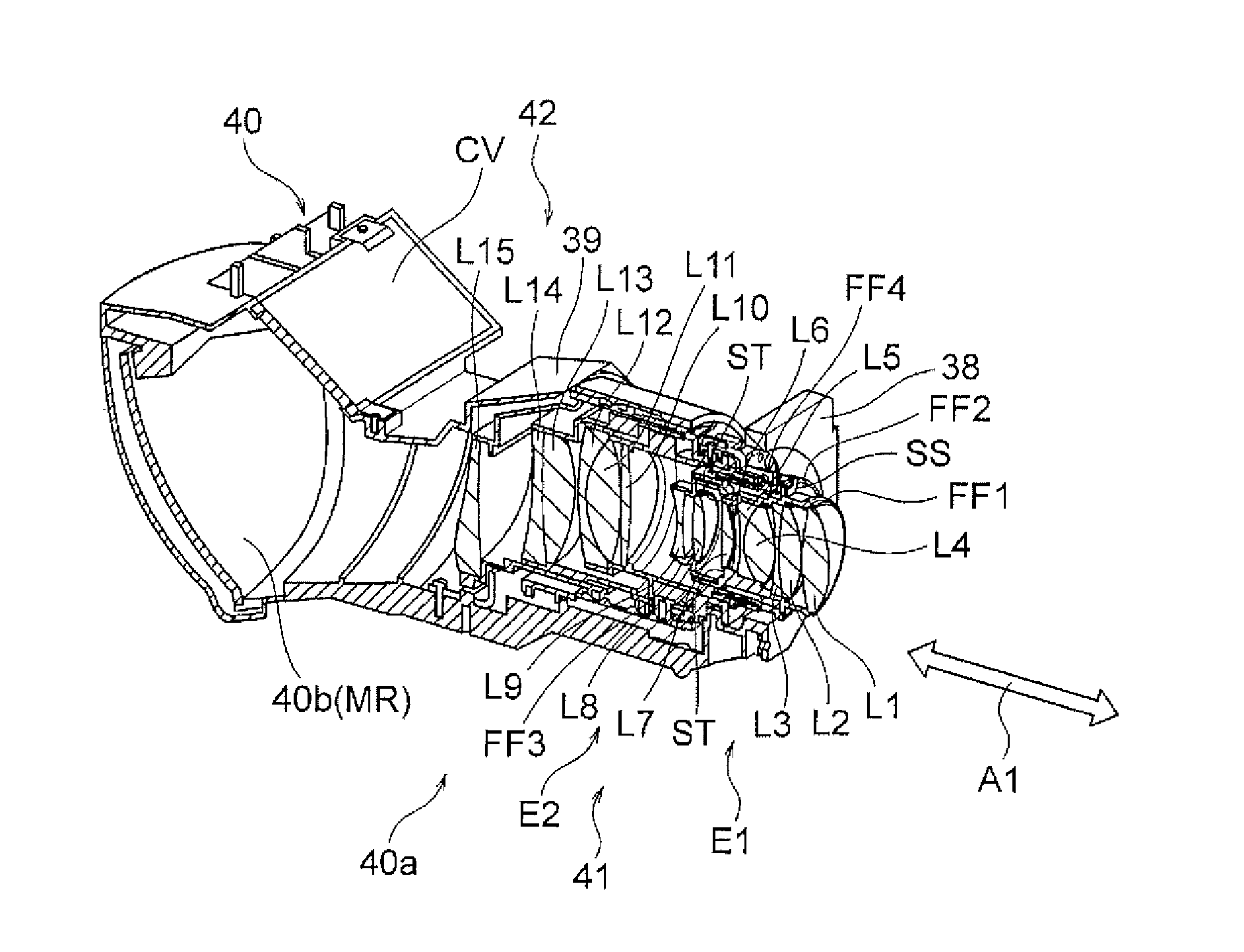
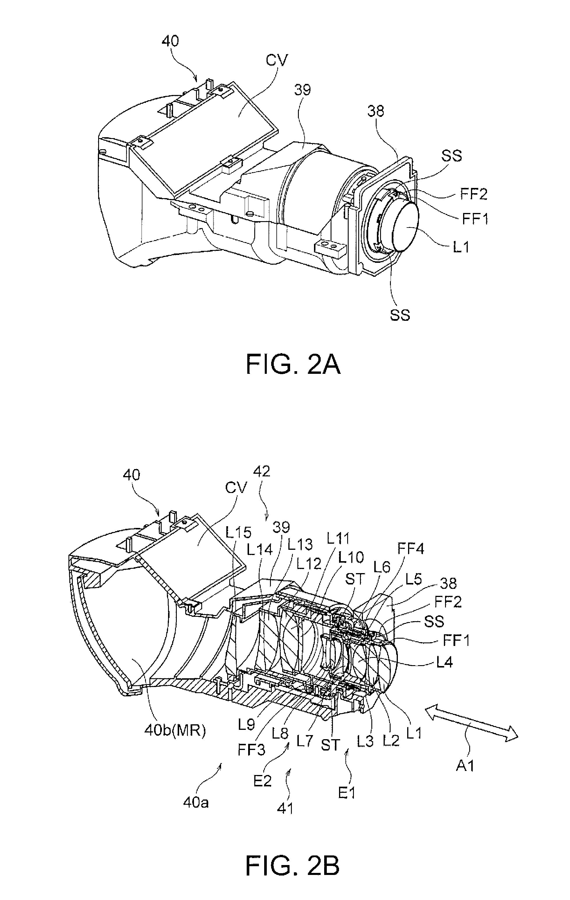
[0061]An example of the projection system 40 will be specifically described below with reference to FIGS. 7 and 8. It is noted that the example corresponds to the embodiment described above.

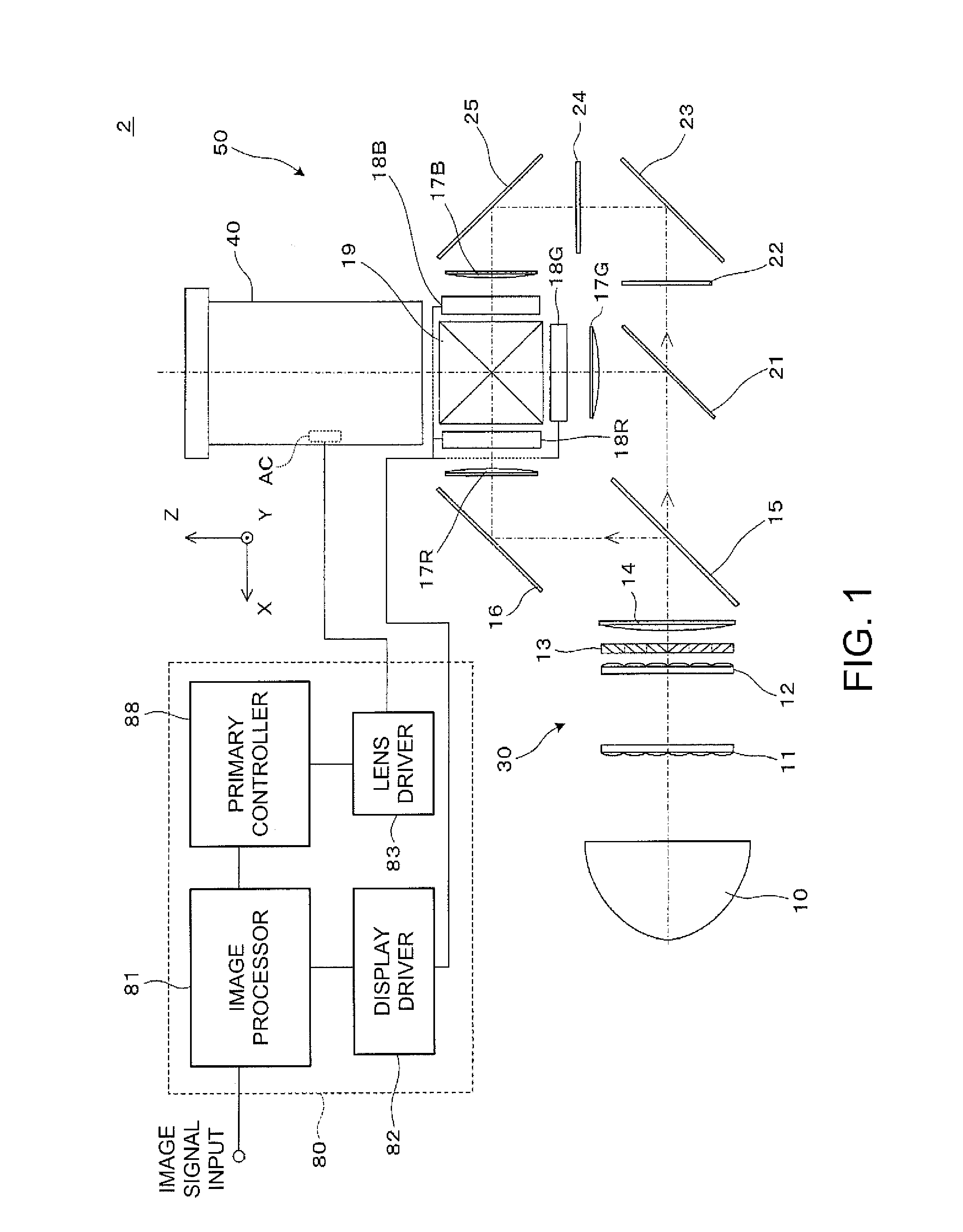
[0062]The projection system 40 according to the example shown in FIGS. 7 and 8 projects an image formed on the display area of the liquid crystal panel 18G (18R, 18B) on the screen that is not shown. A prism PR corresponding to the cross dichroic prism 19 shown in FIG. 1 is disposed between the projection system 40 and the liquid crystal panel 18G (18R, 18B).

[0063]The projection system 40 is formed of the first-first lens group 41 and the first-second lens group 42, which form the first optical group 40a, and the second optical group 40b sequentially arranged from the reduction side. The first-first lens group 41 is formed of the lens group E1 (lenses L1 to L7), which is shifted from the aperture stop ST toward the reduction side, and the lens group E2 (lenses L8 and L9), which is shifted from th...


PUM


Abstract

A feeding mechanism is used to adjust the distance between a reduction side lens group and an object plane for back focus adjustment. A rotation angle adjustment mechanism capable of rotating action independent of rotating action performed in the back focus adjustment is used to adjust the rotation angle by which at least part of the reduction side lens group is rotated.

Description

BACKGROUND[0001]1. Technical Field[0002]The present invention relates to a projection system suitable to be incorporated into a projector that enlarges and projects an image on an image display device and further relates to a projector.[0003]2. Related Art[0004]As a projector and a projection system suitable to be incorporated into a projector, for example, there is a known projector and projection system that use a fixed lens section, a movable lens section, and a concave mirror to reduce inclination of an oblique light flux in oblique projection with respect to the optical axis in order to perform wide-angle projection over a short distance (short-throw projection) while effectively preventing an image-forming light flux from being truncated by a lens barrel (see JP-A-2011-85922).[0005]In general, in a projector, to prevent the screen-side image plane from inclining due to variation in back focal distance (distance from panel surface to projection system), it is important to perfo...

Claims


Application Information

Patent Timeline
IPC IPC(8): G03B21/14G02B13/04G02B17/08G03B21/00G03B21/28G02B13/16G02B7/04
CPCG03B21/142G02B13/16G02B13/04G02B17/08G03B21/005G03B21/28G02B7/04
Inventor TAKEHANA, NAOTO
Owner SEIKO EPSON CORP
Why Eureka
Try Eureka