
Sound source separating device and sound source separating method

a separation device and sound source technology, applied in the field of sound source separation devices and sound source separation methods, can solve the problems of poor separation matrix stability and sound source separation performance degradation, and achieve the effects of accurately separating speech signals, and stabilizing sound source separation performan

Active Publication Date: 2016-12-22
HONDA MOTOR CO LTD
View PDF0 Cites 12 Cited by
  • Summary
  • Abstract
  • Description
  • Claims
  • Application Information

AI Technical Summary

Benefits of technology

The present invention provides a device and method for separating sound sources that can improve the performance of sound source separation. This device can collect speech signals from both the driver and passenger in a vehicle, providing a more accurate recording of the conversation. This can be useful for improving safety and communication in the vehicle.

Problems solved by technology

Accordingly, in the related art, the stability of the separation matrix may be poor until the separation matrix converges, and the sound source separation performance may degrade.

Method used


Image

  • Sound source separating device and sound source separating method
  • Sound source separating device and sound source separating method
  • Sound source separating device and sound source separating method

Examples


first embodiment

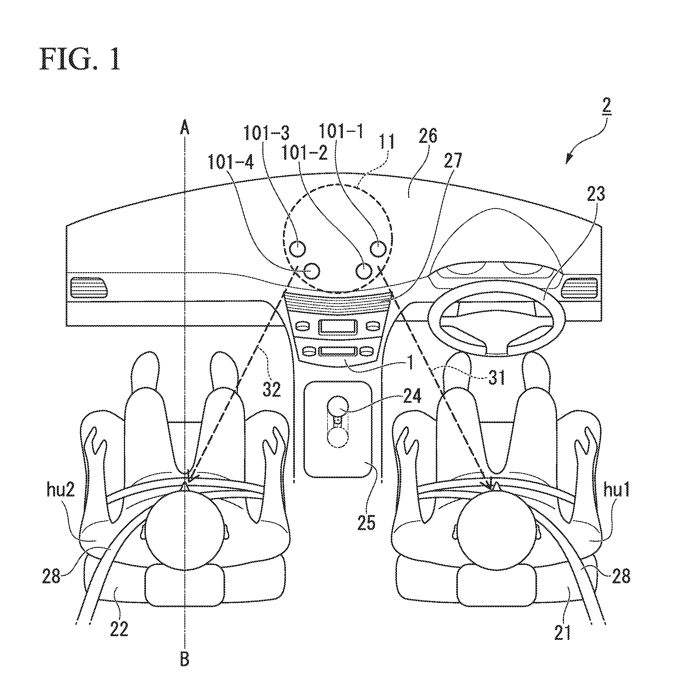
[0048]First, an example of an arrangement of a sound collecting unit 11, which collects sound signals, in a vehicle 2, positions of speakers, and fixed sound source directions will be described below.

[0049]FIG. 1 is a diagram illustrating an example of an arrangement of the sound collecting unit 11, positions of speakers, and fixed sound source directions in a vehicle interior of the vehicle 2 according to this embodiment.

[0050]The vehicle 2 illustrated in FIG. 1 is a so-called right-hand-drive vehicle in which a driver seat 21 is disposed on the right side in the vehicle interior and a passenger seat 22 is disposed on the left side in the vehicle interior. A steering wheel 23 is disposed on the right side in the vehicle interior. A shift panel 25 in which a shift lever 24 protrudes is disposed between the driver seat 21 and the passenger seat 22. The shift panel 25 is disposed at a position protruding upward from the floor of the driver seat 21 and the passenger seat 22. The front ...

second embodiment

[0126]The example in which the number of fixed sound sources is 2 and the number of fixed sound source directions is 2 is described in the first embodiment, but an example in which the number of fixed sound sources is 3 and the number of fixed sound source directions is 3 will be described in this embodiment.

[0127]FIG. 8 is a cross-sectional view of the vehicle 2 taken along line A-B in FIG. 1.

[0128]As illustrated in FIG. 8, a map lamp 29 and a sound collecting unit 11 are disposed on the ceiling of the vehicle 2. A virtual sound source sp is set as a fixed sound source in addition to a driver hu1 and a passenger hu2. Here, the virtual sound source sp is a single virtual sound source virtually including road noise, air conditioner noise (operating sounds and the like), sound signals of a car stereo system, and the like.

[0129]A predetermined direction 33 (for example, a downward direction of the sound collecting unit 11) which is different from a sound source direction 31 and a sound...


PUM


Abstract

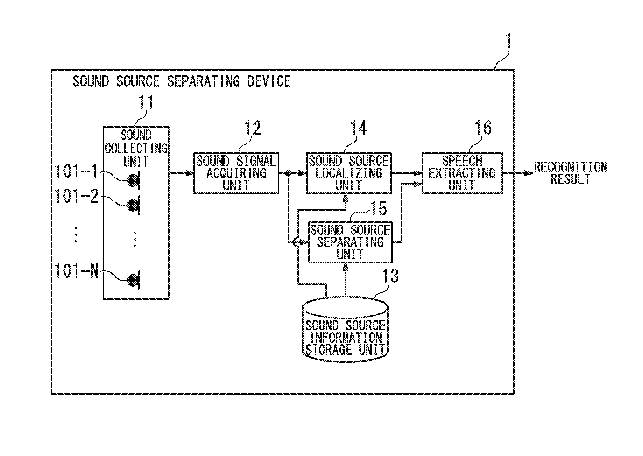
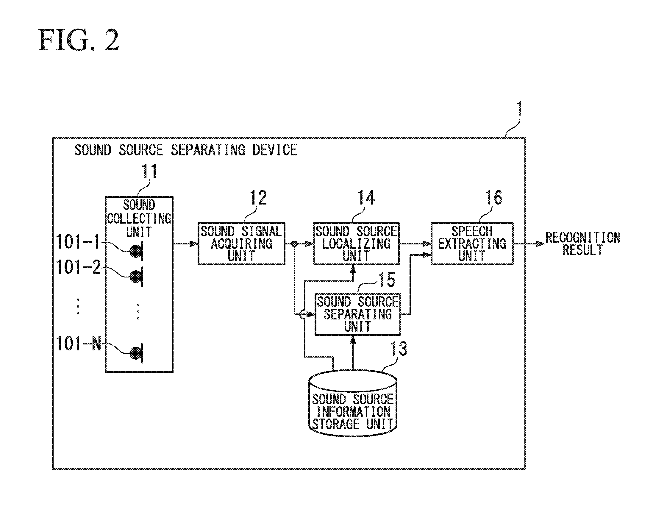
A sound source separating device includes: a sound collecting unit configured to collect sound signals using a plurality of microphones; a sound source localizing unit configured to localize a sound source on the basis of the sound signals collected by the sound collecting unit; a sound source separating unit configured to separate the sound signals collected by the sound collecting unit into sound sources corresponding to the number of fixed sound sources and fixed sound source directions without using the sound source localization result from the sound source localizing unit; and a speech extracting unit configured to extract speech signals of the fixed sound sources on the basis of the sound source localization result from the sound source localizing unit and the sound source separation result from the sound source separating unit.

Description

CROSS-REFERENCE TO RELATED APPLICATION[0001]Priority is claimed on Japanese Patent Application No. 2015-122842, filed on Jun. 18, 2015, the content of which is incorporated herein by reference in its entirety.BACKGROUND OF THE INVENTION[0002]1. Field of the Invention[0003]The present invention relates to a sound source separating device and a sound source separating method.[0004]2. Description of Related Art[0005]In a vehicle, a speech recognition system for operating a navigation system or the like with a voice command has been proposed. In such a speech recognition system, for example, when a vehicle travels on an expressway or when music is played in a vehicle, a speech recognition rate is likely to decrease due to mixture of large noise from the surroundings.[0006]Accordingly, in the speech recognition system, a sound source position of speech of a speaker sitting in a seat is stored as preset information in advance for each seat position. In the speech recognition system, a pro...

Claims


Application Information

Patent Timeline
Patent Type & Authority Applications(United States)
IPC IPC(8): G10L21/028G10L25/84
CPCG10L21/028G10L25/84G10L15/00G10L15/20G10L2021/02166
Inventor NAKADAI, KAZUHIROMIZUMOTO, TAKESHINAKAMURA, KEISUKE
Owner HONDA MOTOR CO LTD
Learn More