
Electrical element, mobile device, and method for manufacturing electrical element

Active Publication Date: 2016-12-22
MURATA MFG CO LTD
View PDF6 Cites 4 Cited by
  • Summary
  • Abstract
  • Description
  • Claims
  • Application Information

AI Technical Summary

Benefits of technology

The present invention provides an electrical element that has a characteristic that is influenced by a nearby metal member, which is especially significant at high frequency bands like antennas. The invention avoids variations in the position between the flexible substrate and the ground conductor, which ensures consistent performance and function. Additionally, the invention allows for the use of a non-patterned ground conductor and lead-out wiring, further reducing the likelihood of variations in the electrical element's characteristic.

Problems solved by technology

Further, for example, when a flexible portion and a rigid portion are formed by a multilayer substrate including a lamination of a plurality of base layers, and removing unnecessary portions therefrom, a great amount of materials is wasted.

Method used


Image

  • Electrical element, mobile device, and method for manufacturing electrical element
  • Electrical element, mobile device, and method for manufacturing electrical element
  • Electrical element, mobile device, and method for manufacturing electrical element

Examples


first preferred embodiment

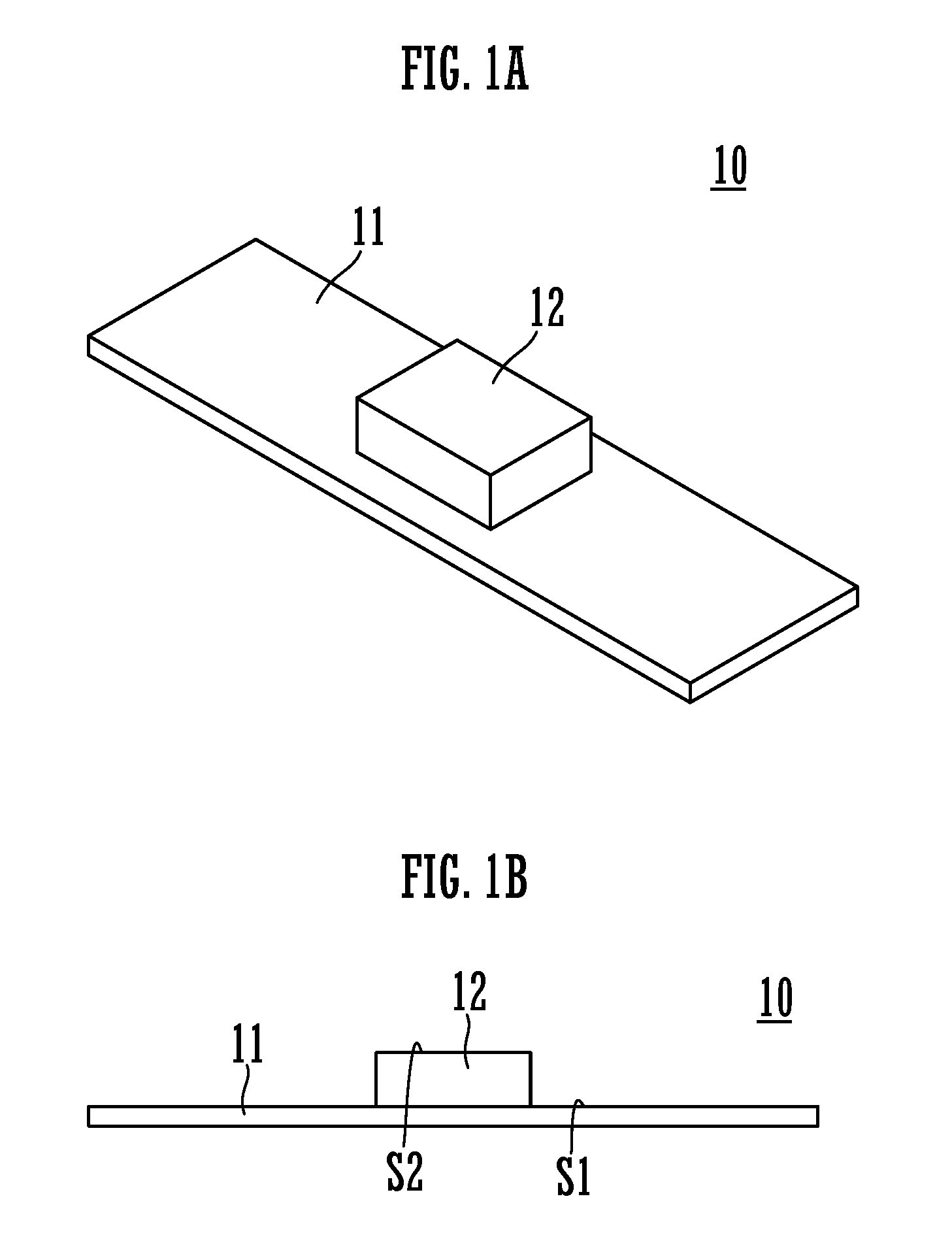
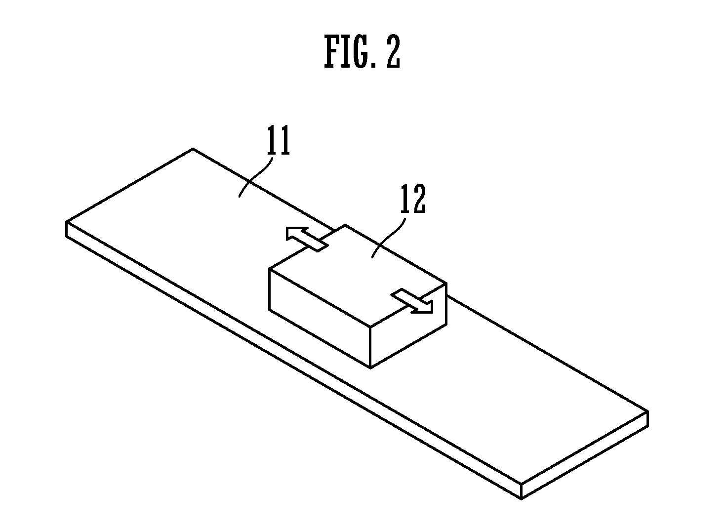
[0054]A description will be given of an electrical element according to a first preferred embodiment of the present invention. FIG. 1A is an external perspective view of the electrical element 10. FIG. 1B is a side view of the electrical element 10. The electrical element 10 includes a quadrangular plate-shaped flexible antenna 11 and a rectangular parallelepiped rigid member 12. The flexible antenna 11 is flexible, and the rigid member 12 is higher in rigidity than the flexible antenna 11 and is rigid. The rigid member 12 is directly joined to a main surface S1 of the flexible antenna 11. In other words, the rigid member 12 and the flexible antenna 11 are joined to each other having no other member (e.g., an adhesive agent) interposed between them. The flexible antenna 11 is an example of the flexible substrate.

[0055]The flexible antenna 11 preferably includes laminated flexible base layers and a conductor pattern (not shown) provided at the base layers. The base layers of the flex...

second preferred embodiment

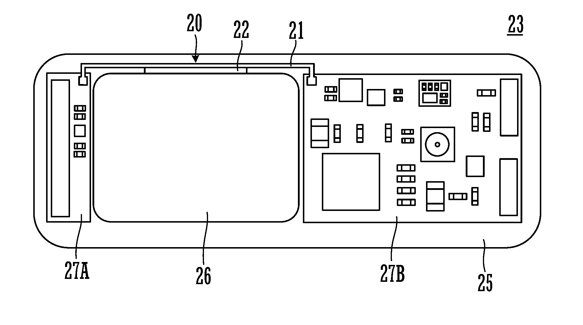
[0072]A description will be given of a mobile device 23 according to a second preferred embodiment of the present invention. FIG. 3 is a plan view showing the inside of the mobile device 23. The mobile device 23 includes an electrical element 20, a housing 25, a battery pack 26, and circuit boards 27A and 27B.

[0073]The electrical element 20 includes a transmission line and a rigid member 22 higher in rigidity than the transmission line 21. The transmission line 21 corresponds to the flexible substrate. At least one of the transmission line 21 and the rigid member 22 is made of thermoplastic resin. A conductor pattern that defines at least a portion of a section that performs the main function (the function of transmitting signals) of the electrical element 20 is provided at the transmission line 21. No conductor pattern that defines the section that performs the main function of the electrical element 20 is provided at the rigid member 22. The transmission line 21 and the rigid memb...

third preferred embodiment

[0077]A description will be given of a mobile device 33 according to a third preferred embodiment of the present invention. FIG. 4 is a cross-sectional view partially showing the mobile device 33. The mobile device 33 includes an electrical element 30, a motherboard 35, and an inductor bridge 36.

[0078]The electrical element 30 includes a flexible antenna 11 and rigid members 32A and 32B being higher in rigidity than the flexible antenna 11. At least one of the flexible antenna 11 and the rigid members 32A and 32B is made of thermoplastic resin. A conductor pattern that defines at least a portion of a section that performs the main function of the electrical element 30 is provided at the flexible antenna 11. No conductor pattern that defines the section that performs the main function of the electrical element 30 is provided at the rigid members 32A and 32B. The flexible antenna 11 and the rigid members 32A and 32B have their respective opposing surfaces directly joined to each other...


PUM

PropertyMeasurementUnit
Thicknessaaaaaaaaaa
Flexibilityaaaaaaaaaa
Electrical conductoraaaaaaaaaa

Abstract

An electrical element includes a flexible antenna and a rigid member higher in rigidity than the flexible antenna. At least one of the flexible antenna and the rigid member is made of thermoplastic resin. A conductor pattern defining at least a portion of a section that performs the main function of the electrical element is provided at the flexible antenna. No conductor pattern that performs the main function of the electrical element is provided at the rigid member. Opposing surfaces of the flexible antenna and the rigid member are directly joined to each other.

Description

CROSS REFERENCE TO RELATED APPLICATIONS[0001]This application claims the benefit of priority to Japanese Patent Application 2014-064956 filed Mar. 27, 2014 and is a Continuation Application of PCT / JP2014 / 082209 filed on Dec. 5, 2014. The entire contents of each application are hereby incorporated herein by reference.BACKGROUND OF THE INVENTION[0002]1. Field of the Invention[0003]The present invention relates to an electrical element including a flexible substrate and a rigid member, a mobile device including the electrical element, and a method for manufacturing the electrical element.[0004]2. Description of the Related Art[0005]An electrical element that includes a flexible substrate and a rigid member being higher in rigidity than the flexible substrate is disclosed in, for example, Japanese Unexamined Patent Application Publication No. 2009-218447. Japanese Unexamined Patent Application Publication No. 2009-218447 discloses that, a resin reinforcement plate (a rigid member) being...

Claims


Application Information

Patent Timeline
IPC IPC(8): H01Q1/24H01Q1/48H01Q1/38
CPCH01Q1/243H01Q1/48H01Q1/38H05K2201/0129H05K1/16H05K2201/10098H05K3/0064H05K2201/056H05K1/0393H05K1/14H05K1/02
Inventor OKAMOTO, BUNTAMORITA, ISAMUISHINO, SATOSHISASAKI, JUNOTSUBO, YOSHIHITOARAKI, KEISUKESAKAI, NORIO
Owner MURATA MFG CO LTD
Features
  • Generate Ideas
  • Intellectual Property
  • Life Sciences
  • Materials
  • Tech Scout
  • Unparalleled Data Quality
  • Higher Quality Content
  • 60% Fewer Hallucinations
Learn More