Input power appraisal based wireless power system

a wireless power system and input power technology, applied in the direction of battery data exchange, exchanging data chargers, transportation and packaging, etc., can solve the problems of unsatisfactory power needs of wireless power transmitters, adverse effects on battery reliability and life, user experience unpleasant, etc., to overcome unstable power transfer behavior

Active Publication Date: 2016-12-22
WIPQTUS
View PDF6 Cites 48 Cited by
  • Summary
  • Abstract
  • Description
  • Claims
  • Application Information

AI Technical Summary

Benefits of technology

[0010]For a period of time following the start of power transfer, the wireless power transmitter actively monitors for unstable power transfer behavior. Depending on various factors such as operating efficiency of the wireless power transmitter and wireless power receiver, positional alignment between the wireless power transmitter's transmit power interface and the wireless receiver's receive power interface, etc., the selected input power source may not yet be able to source sufficient power into the wireless power system for the wireless power receiver to deliver its configured maximum output power to its downstream passive or active load. If there is an unstable power transfer behavior, the wireless power transmitter suitably reduces its efficiency estimates in every pass to yield maximum output power limit and input power threshold values that are lower than those values computed and communicated in the previous pass. With this approach, if ever there were any unstable power transfer behavior, the wireless power transmitter will trap and eliminate such an unstable power transfer behavior right in the initial period of charging. The wireless power system overcomes unstable power transfer behavior by computing, configuring and fine-tuning a sustainable maximum output power limit of the wireless power receiver based of the maximum available power from the wireless power transmitter's input power sources.

Problems solved by technology

In practical day-to-day wireless charging, there are scenarios where the wireless power transmitter cannot satisfy the power needs of one or more wireless power receivers that are placed on top or in the vicinity of it because of limitations of its input power source.
Battery charging of the end device will repeatedly start and stop which has an adverse effect on the reliability and life of the battery.
The user experience will be unpleasant and the consumer may steer away from wireless charging as they may not recognize what is causing such an unstable behavior.
As a result, the consumer may be confused and frustrated with varying wireless charging behavior and performance depending on the USB port type into which the wireless power transmitter is plugged in.
The wireless power transfer becomes unstable whenever the wireless power transmitter, by virtue of the limitations of input power source(s), is unable to satisfy the simultaneous dynamic power needs of one or more wireless power receivers placed on top or in the vicinity of the wireless power transmitter.
Hence, there is a long felt but unresolved need for a wireless power charging system that overcomes such an unstable power transfer behavior.

Method used


Image

  • Input power appraisal based wireless power system
  • Input power appraisal based wireless power system
  • Input power appraisal based wireless power system

Examples


first embodiment

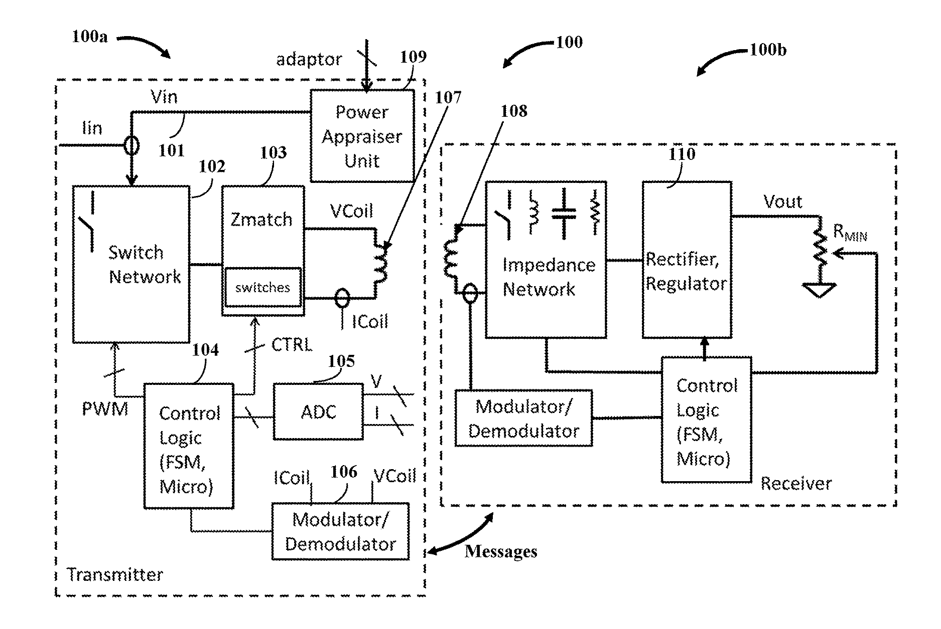
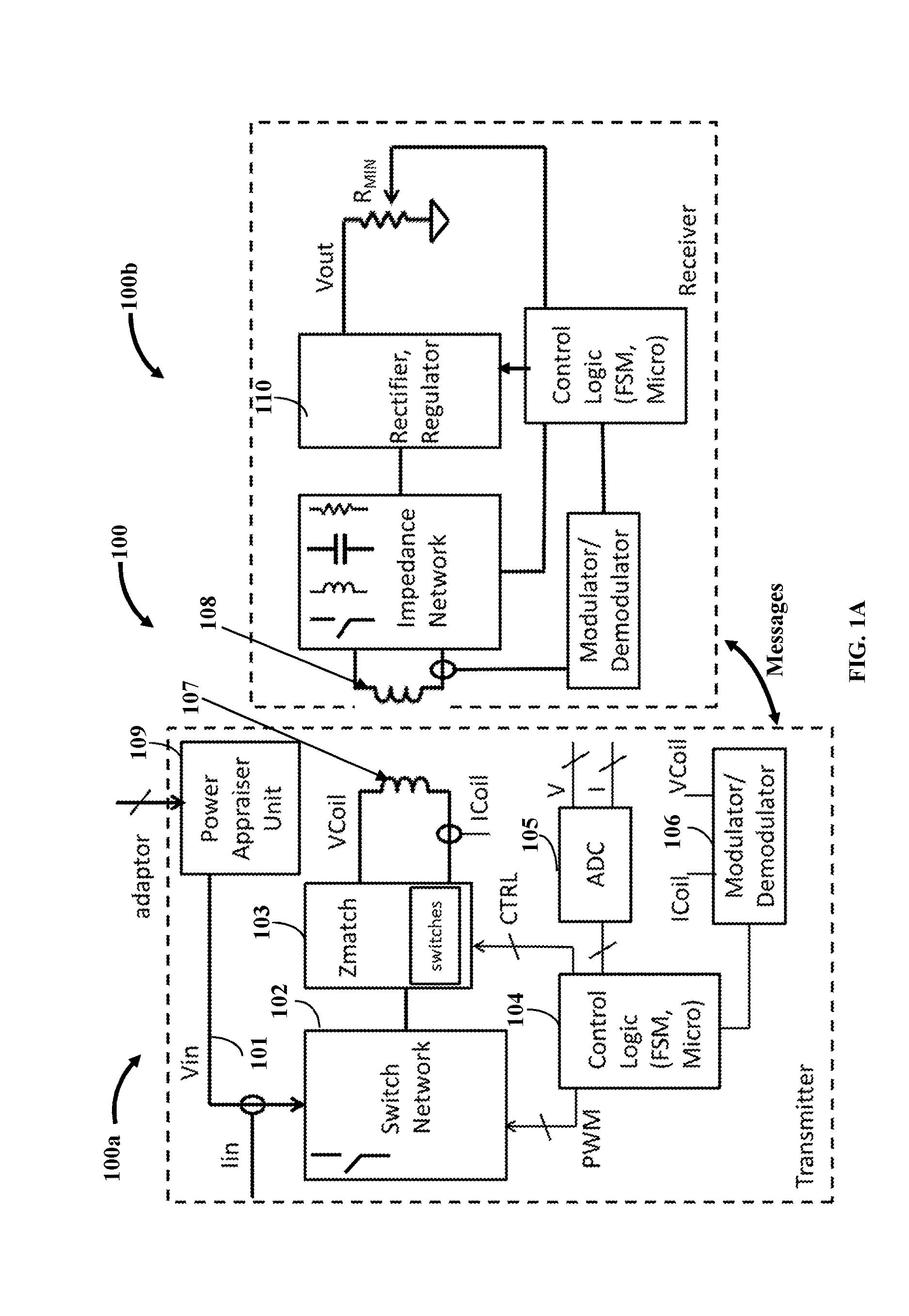
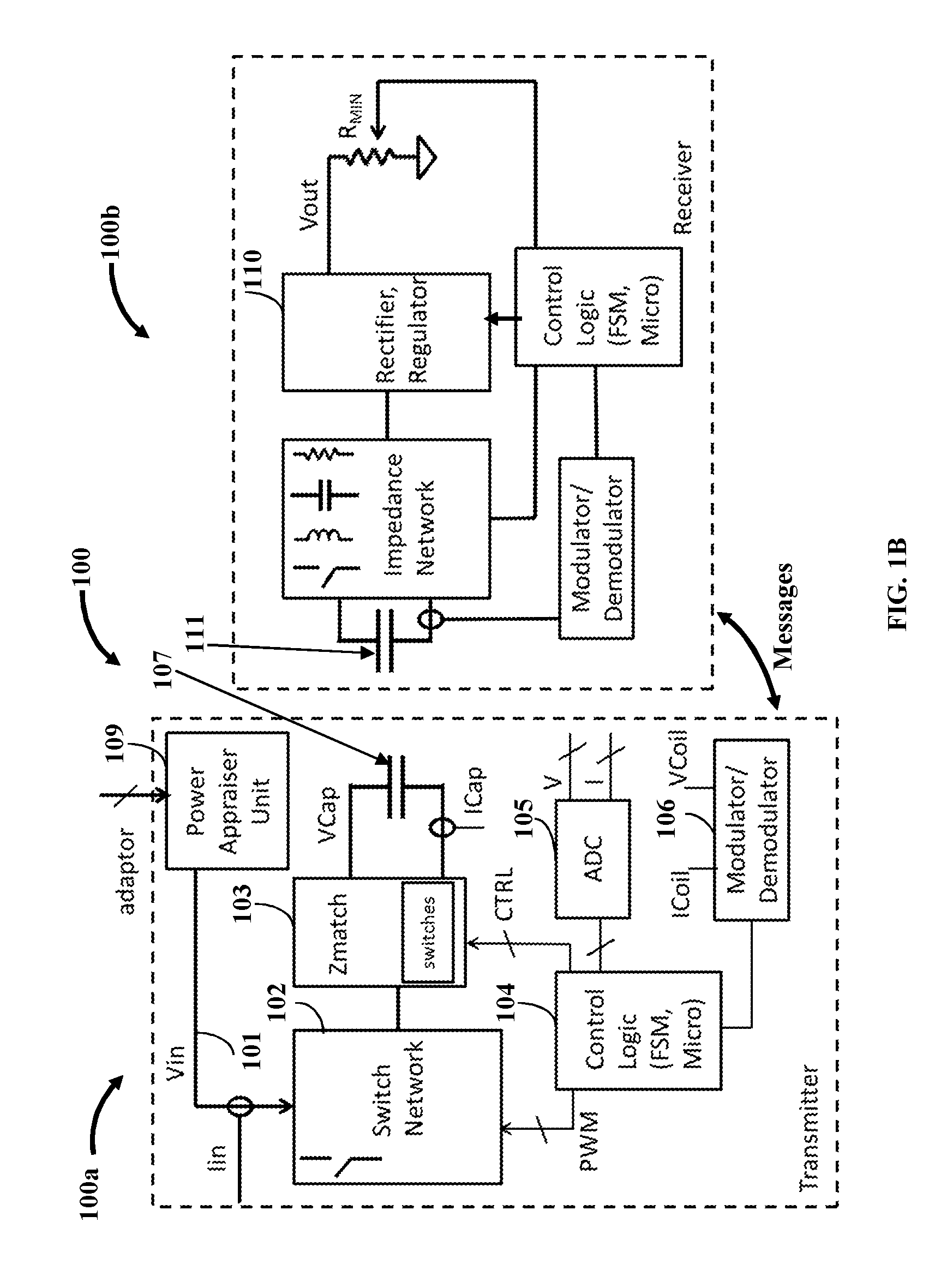
[0025]FIG. 2A exemplarily illustrates the power appraiser circuit 109 of the wireless power transmitter 100a. The power appraiser circuit 109 is exemplarily illustrated as a “power appraiser unit” in FIG. 2A. The power appraiser circuit 109 has a variable load 203 exemplarily illustrated as “RLOAD” in FIGS. 2A-2B that is controlled by a control logic circuit 104, for example, a state machine, a microcontroller, etc. The variable load 203 is connected to a path carrying the input power to the power inverter. The variable load 203 is configured to vary load characteristics of this path. The variable load RLOAD 203 can be implemented, for example, using resistors, MOSFETs, transistors such as bipolar transistors, duty cycle varied switching, etc. The power appraiser circuit 109 determines the maximum input power available to the power inverter by varying the RLOAD 203 from a high resistance to a low resistance while monitoring the input power which is a product of IIN and VIN sourced f...

second embodiment

[0026]FIG. 2B exemplarily illustrates the power appraiser circuit 109 of the power appraisal based wireless power transmitter 100a. The power appraiser circuit 109 is exemplarily illustrated as a “power appraiser unit” in FIG. 2B. The power appraiser unit has a variable load 203 exemplarily illustrated as “RLOAD” in FIGS. 2A-2B, that is controlled by a logic circuit 201, for example, a state machine, a microcontroller, etc. The power appraisal is performed by having an intermediate stage, for example, a regulator or a switch 204 before the point of observation, that is the maximum input power available to the power inverter is measured after regulator or a switch 204. The regulator or the switch 204 is operably coupled to the variable load 203 connected to the path carrying the input power to the power inverter. The regulator maintains a constant input voltage to the variable load 203 and the switch 204 is used to configure a path for the flow of input current. The power appraiser c...

third embodiment

[0027]FIG. 2C exemplarily illustrates the power appraiser circuit 109 of the power appraisal based wireless power transmitter 100a. The power appraiser circuit 109 is exemplarily illustrated as a “power appraiser unit” in FIG. 2C. One or more input pins of the power appraiser circuit 109 is configured to receive power ratings of the input power sources that indicate the maximum available power from the input power sources. In the first approach, the power appraisal is performed on the basis of an explicit indication on a separate pin. For example, if the input pin is at a 3.3V TTL logic level 1 (>2.2 Volts), then the maximum available power of the power source associated with the pin may be considered as 10 Watts. If the same input pin was at a 3.3V TTL logic level 0 of (2.2 Volts), then the maximum available power of the power source X may be considered 30 W. If pinA and pinB were both at 3.3V TTL logic level 0 (104 and the external controller. In an embodiment of this approach, po...


PUM


Abstract

A wireless power system (WPS) has a wireless power transmitter (WPT) that appraises an input power available to a power inverter from one or more input power sources. The WPT comprises the power inverter that wirelessly transmits power to a wireless power receiver (WCR) of the WPS, and a power appraiser circuit (PAC). The PAC ascertains maximum input power available to the power inverter from the input power sources. The PAC includes a variable load connected to a path carrying the input power to the power inverter or one or more input pins that receive power ratings of the input power sources that indicate available maximum input power from the input power sources. The ascertaining of maximum input power available to the power inverter from the input power sources appraises the input power available to the power inverter. The WCR receives information representing maximum power deliverable by the WPT.

Description

CROSS REFERENCE TO RELATED APPLICATIONS[0001]This application is a continuation-in-part of application Ser. No. 13 / 950,288 filed in the United States Patent and Trademark Office on Jul. 25, 2013 which claims benefit from U.S. Provisional Application No. 61 / 676,916 filed on Jul. 28, 2012.BACKGROUND[0002]In practical day-to-day wireless charging, there are scenarios where the wireless power transmitter cannot satisfy the power needs of one or more wireless power receivers that are placed on top or in the vicinity of it because of limitations of its input power source. For example, a wireless power transmitter connected to a USB 2.0 port can only draw 2.5 Watts (W) of power from the USB port. A wireless power receiver, external or integrated into an end device such as a smartphone, tablet, etc., may be positioned on top of such a wireless power transmitter to receiver power wirelessly from the wireless power transmitter to charge the end device. During charging, if the wireless power r...

Claims


Application Information

Patent Timeline
Patent Type & Authority Applications(United States)
IPC IPC(8): H02J7/02H02J50/10H02J7/04
CPCH02J7/027H02J50/10H02J7/045H02J7/025H02J50/40H02J50/80H02J50/05H02J7/00036H02J7/00047H02J7/04H02J7/0014H02J7/007182H02J3/322H02J7/00714
Inventor SANKAR, GANAPATHY
Owner WIPQTUS
Why Eureka
Try Eureka