Launching apparatus for underwater payload

a technology for underwater payloads and launchers, applied in the direction of propulsion systems, torpedo launchers, mechanical energy handling, etc., can solve the problems of radiation noise, failure to convert energy into operation, and failure to achieve the effect of efficiently obtaining sufficient water pressur

Active Publication Date: 2016-12-22
KOBE STEEL LTD
View PDF6 Cites 11 Cited by
  • Summary
  • Abstract
  • Description
  • Claims
  • Application Information

AI Technical Summary

Benefits of technology

[0007]It is an object of the present invention to provide an apparatus for launching underwater payloads with water pressure, the apparatus being capable of efficiently obtaining sufficient water pressure for launching the underwater payload regardless of electric resistance of water.

Problems solved by technology

The apparatuses using pneumatic pressure as explained above involves conversion of pressure energy of the air into operation energy for actuating the turbine and the piston, while having a possibility of failing to convert a part of the pressure energy into the operation energy.
The pressure energy failed to be converted into the operation energy changes to, for example, vibration energy, causing radiation noise.
The technique for passing the electric current through the water (the seawater) in the conduit to generate the electromagnetic force, however, involves a problem that the electric resistance of the water (the seawater) affects the generation of the electromagnetic force to prevent water pressure from being sufficiently increased.
Applying an excessively high voltage for obtaining a large electromagnetic force enough to overcome the electric resistance may involve electrolysis of the water (the seawater) in the conduit.

Method used


Image

  • Launching apparatus for underwater payload
  • Launching apparatus for underwater payload
  • Launching apparatus for underwater payload

Examples


Embodiment Construction

[0019]There will be explained below preferred embodiments of the present invention.

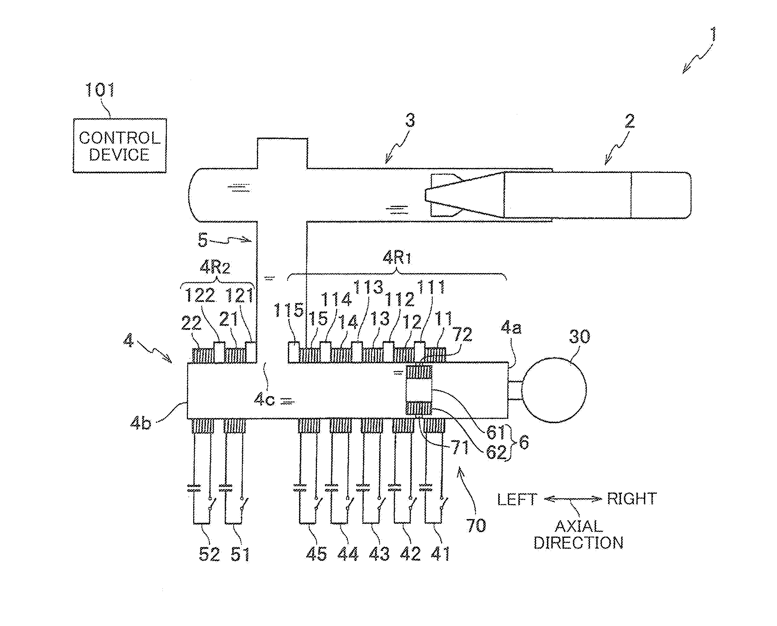
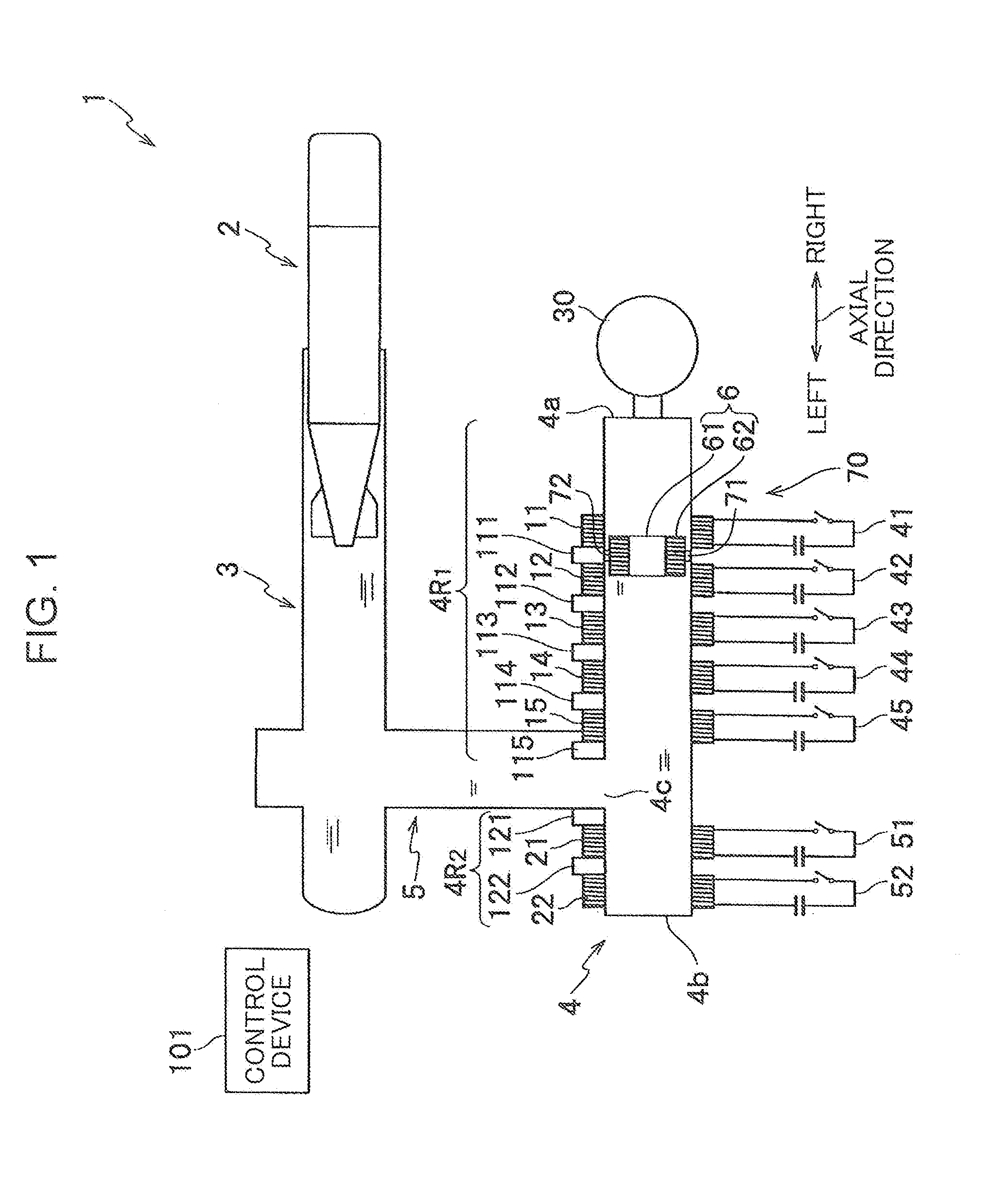
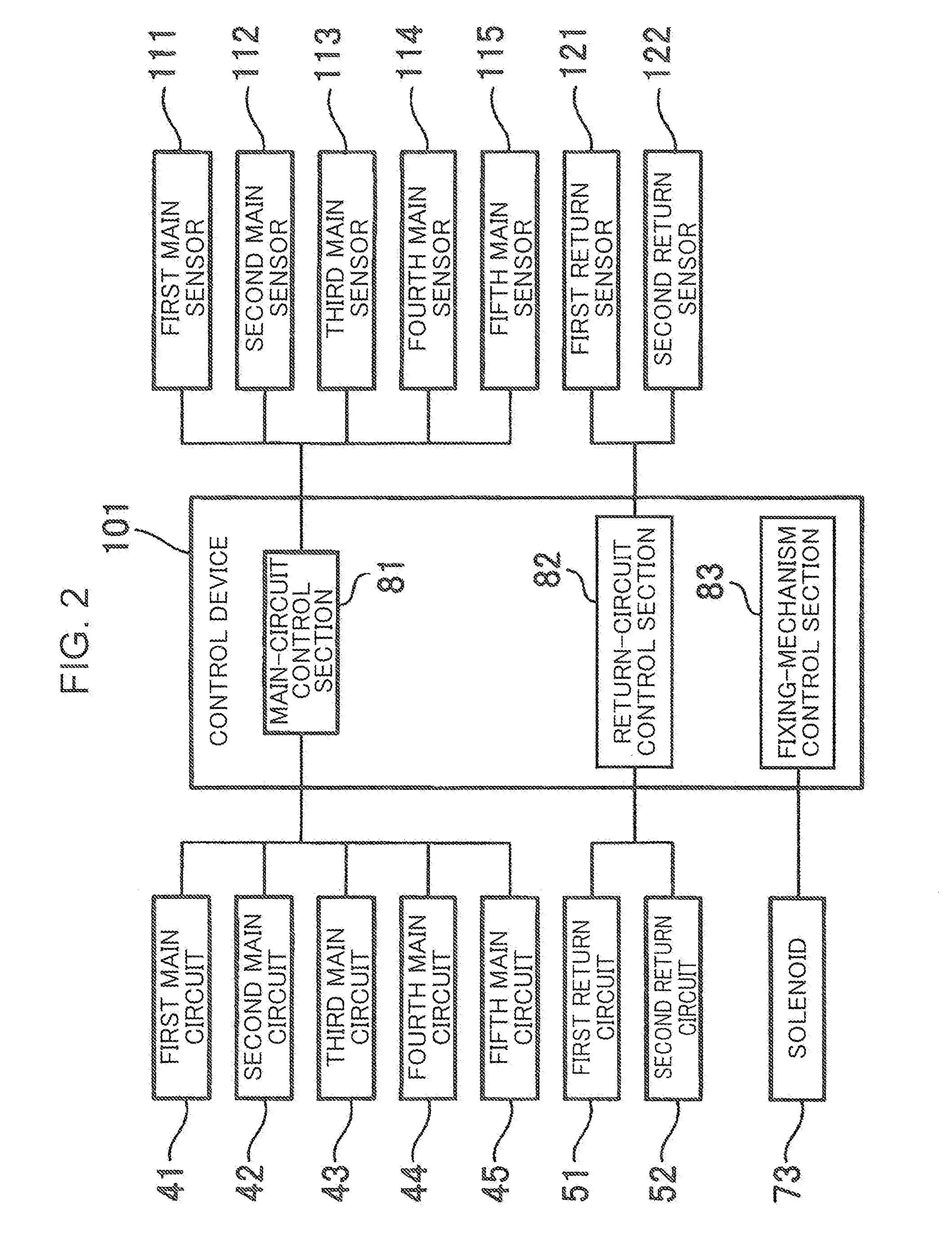
[0020]FIG. 1 shows a launching apparatus 1 for underwater payloads according to the present embodiment. The launching apparatus 1 for underwater payloads includes: a launch tube 3 in which an underwater payload 2 is loaded; a conduit 4 for applying water pressure for launching the underwater payload 2 to the launch tube 3; a pipe 5 which is a communicating portion bringing the launch tube 3 and the conduit 4 into communication with each other; a moving object 6 disposed in the conduit 4; a plurality of conduit coils; a plurality of return coils; a plurality of main circuits; a plurality of return circuits; a plurality of sensors; and a control device 101.

[0021]The conduit 4 extends axially, that is, extends in the axial direction, including a first end portion 4a and a second end portion 4b, which are axially opposite end portions. The pipe 5 is connected to a portion located behind the underwater pay...


PUM


Abstract

Provided is a launching apparatus capable of efficiently obtaining water pressure sufficient for launching an underwater payload, including a launch tube, a conduit including a first end portion and a communicating portion communicating with the launch tube, a plurality of conduit coils to axially aligned in a first region between the first end portion and the communicating portion, a plurality of main circuits passing an electric current through respective conduit coils, and a main-circuit control section. The main-circuit control section controls operation of the main circuits to pass electric currents through the conduit coils to generate an axial first magnetic field in the conduit and thereby cause an axial second magnetic field in a moving object, thereby moving the moving object in an advance direction toward a second end portion.

Description

TECHNICAL FIELD[0001]The present invention relates to a launching apparatus for underwater payloads.BACKGROUND ART[0002]Japanese Patent No. 2936079 (Patent Literature 1) discloses a launching apparatus for underwater payloads, the apparatus including a launch tube in which an underwater payload is loaded and a water supply device that supplies boosted water to the launch tube. The water supply device includes a pneumatically-driven turbine, which includes an impellers rotated underwater to increase water pressure.[0003]US Patent Specification No. 2837971 (Patent Literature 2) discloses a launching apparatus for underwater payloads, the apparatus including a launch tube in which an underwater payload is loaded and a conduit communicating with the launch tube. The conduit is filled with water and a piston is disposed therein. The piston is pneumatically driven to reciprocally move in the conduit, thereby increasing water pressure in the conduit.[0004]The apparatuses using pneumatic pr...

Claims


Application Information

Patent Timeline
Patent Type & Authority Applications(United States)
IPC IPC(8): H02K41/02F41F3/08H02K7/14
CPCH02K41/02F41F3/08H02K7/14F41B6/003F41F3/10
Inventor MATSUI, HIROYOSHI
Owner KOBE STEEL LTD
Why Eureka
Try Eureka