Eureka AIR delivers breakthrough ideas for toughest innovation challenges, trusted by R&D personnel around the world.

Torque generation system, attitude control system for spacecraft, and relative position and velocity control system for spacecraft

a technology of attitude control system and torque generation system, which is applied in the direction of spacecraft, transportation and packaging, aircraft, etc., can solve the problems of limited amount of fuel mountable on the spacecraft, difficult to achieve the effect of existing wheels, and limited thruster operability, etc., to achieve small torque and high precision

Inactive Publication Date: 2016-12-29
JAPAN AEROSPACE EXPLORATION AGENCY
View PDF3 Cites 7 Cited by
  • Summary
  • Abstract
  • Description
  • Claims
  • Application Information

AI Technical Summary

Benefits of technology

[0025]The attitude control system may further includes: an attitude detector configured to detect the attitude of the spacecraft; and a target attitude setting unit configured to set a target attitude of the spacecraft, wherein the attitude controller may control the electricity generation ratio of each of the plurality of solar array panels and / or solar array panel divisions to generate torque that decreases a difference between a current attitude detected by the attitude detector and the target attitude.
[0039]Still another aspect of the present invention is to provide a system for controlling a relative position and / or a relative velocity of a first spacecraft and a second spacecraft, including: the first spacecraft and the second spacecraft each including a solar array panel; and a relative position and velocity controller configured to control an electricity generation ratio of each of the solar array panels of the first spacecraft and the second spacecraft to cause each of the first spacecraft and the second spacecraft to generate thrust that changes the relative position and / or velocity of the first spacecraft and the second spacecraft.
[0043]The relative position and velocity controller may put the solar array panel of the first spacecraft in a maximum output state.
[0051]The torque generator according to the present invention can generate very small torque by using solar array panels that are also used as components constituting a spacecraft.
[0052]The attitude control system for a spacecraft and the relative position and velocity control system for a spacecraft according to the present invention can control the attitude of the spacecraft and control the relative position and velocity of the spacecraft with high precision and without causing turbulence, the attitude and the relative position and velocity being controlled by using the solar array panels mounted on the spacecraft without the necessity of mounting an additional device thereon.

Problems solved by technology

However, the amount of fuel mountable on a spacecraft is limited, and the thruster is not operable once the fuel is exhausted.
As illustrated in Table 1, the Solar-B project requires a degree of attitude stabilization which is difficult for existing wheels to achieve.

Method used


Image

  • Torque generation system, attitude control system for spacecraft, and relative position and velocity control system for spacecraft
  • Torque generation system, attitude control system for spacecraft, and relative position and velocity control system for spacecraft
  • Torque generation system, attitude control system for spacecraft, and relative position and velocity control system for spacecraft

Examples


first embodiment

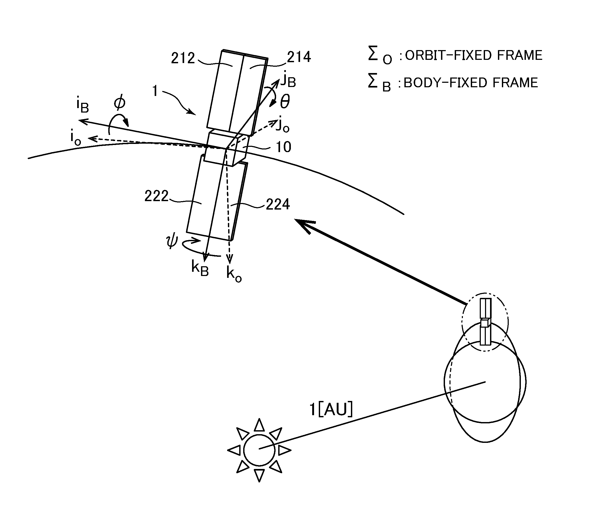
[0081]FIG. 4 is an external view of a satellite 1 as a spacecraft according to a first embodiment of the present invention. The satellite 1 is a 2t-class satellite, which includes a satellite body 10 and two solar array panels 21 and 22. The satellite body 10 has a cubic shape with one side being 2 m and the center of the cube being the center of mass. The solar array panels 21 and 22 have rectangular light receiving surfaces 210 and 220 with a shorter side being 3 m and a longer side being 10 m. The solar array panels 21 and 22 have the aforementioned configuration 2 with aluminum being vapor-deposited on the surface opposite to the light receiving surface. The solar array panels 21 and 22 are completely axially symmetrically arranged for coordinate axes of a later-described body-fixed frame, with respect to the center of mass of the satellite body 10. The solar array panels 21 and 22 include solar cell arrays 212, 214, 222, and 224 which are divisions of the solar array panels. Th...

second embodiment

[0117]FIG. 12 illustrates external appearance and arrangement of a first satellite 41 as a first spacecraft and a second satellite 42 as a second spacecraft according to a second embodiment of the present invention. The first satellite 41 and the second satellite 42 are solar-sailing ultra-small satellites, which include satellite bodies 410 and 420 and solar array panels 411 and 421, respectively. The satellite bodies 410 and 420 each have a cubic shape with one side being 0.1 m. The solar array panels 411 and 421 have square light receiving surfaces 4110 and 4210 with one side being 0.75 m, respectively. The satellite bodies 410 and 420 are arranged in the center of surfaces opposite to the light receiving surfaces of the solar array panels 411 and 421, respectively.

[0118]FIG. 13 illustrates the entire configuration of a system 4 for controlling a relative position and / or relative velocity of the satellite 41 as a first spacecraft and the satellite 42 as a second spacecraft accord...


PUM


Abstract

A torque generation system includes: a plurality of solar array panels and / or solar array panel divisions; and a torque controller configured to control an electricity generation ratio of each of the plurality of solar array panels and / or solar array panel divisions to generate torque.

Description

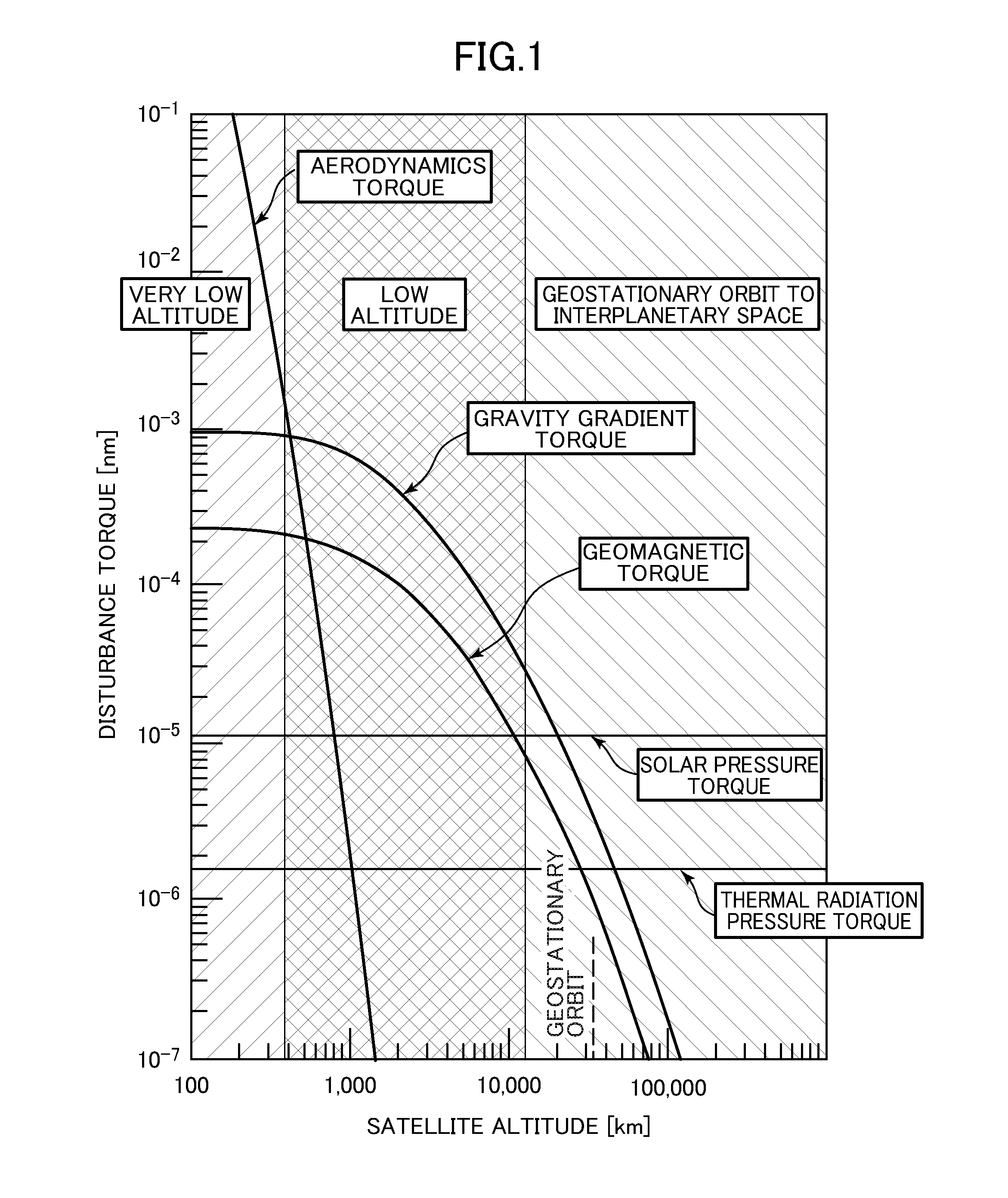
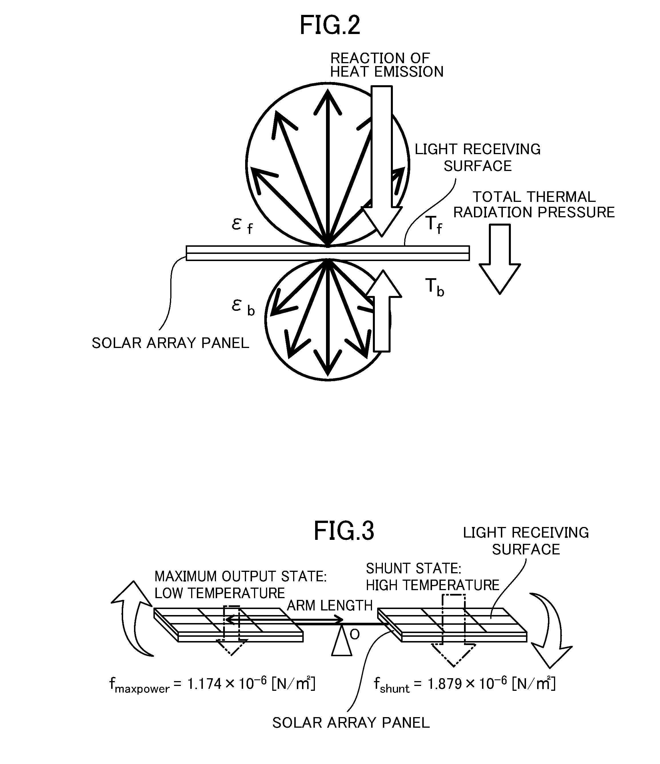
BACKGROUND OF THE INVENTION[0001]Field of the Invention[0002]The present invention relates to torque generation systems, attitude control systems for a spacecraft, and relative position and velocity control systems for a spacecraft. The present invention more particularly relates to a torque generation system, an attitude control system for a spacecraft, and a relative position and velocity control system for a spacecraft, which use a thermal radiation pressure generated from a solar array panel.[0003]Description of the Related Art[0004]The attitude of spacecraft, such as satellites and space probes, is disturbed by disturbance torque. FIG. 1 is an explanatory view of various kinds of disturbance torque based on computation examples of disturbance torque with respect to the altitude of earth orbiting satellites, which is illustrated in “Recent Trends in Three-Axis Stabilized Satellites” by Susumu Nishida in the Journal of the Japan Society for Aeronautical and Space Sciences, Vol. 2...

Claims


Application Information

Patent Timeline
Patent Type & Authority Applications(United States)
IPC IPC(8): B64G1/24B64G1/44B64G1/36H02S40/30
CPCB64G1/24H02S40/30B64G1/361B64G1/365B64G1/443B64G1/36B64G1/244Y02E10/50B64G1/10B64G1/34B64G1/407B64G1/44
Inventor MORI, OSAMUKAWAGUCHI, JUNICHIROSHIRASAWA, YOJICHUJO, TOSHIHIROAKATSUKA, KOSUKE
Owner JAPAN AEROSPACE EXPLORATION AGENCY
Why Eureka
Eureka Blog
Learn More