
Operating control method of a motorized driving device of a home automation installation

a technology of home automation and operating control method, which is applied in the direction of position/direction control, transmission system, building components, etc., can solve the problem of over-cost of the motorized driving device, and achieve the effect of avoiding depletion of at least one battery and reducing electricity consumption

Active Publication Date: 2016-12-29
SIMU
View PDF1 Cites 4 Cited by
  • Summary
  • Abstract
  • Description
  • Claims
  • Application Information

AI Technical Summary

Benefits of technology

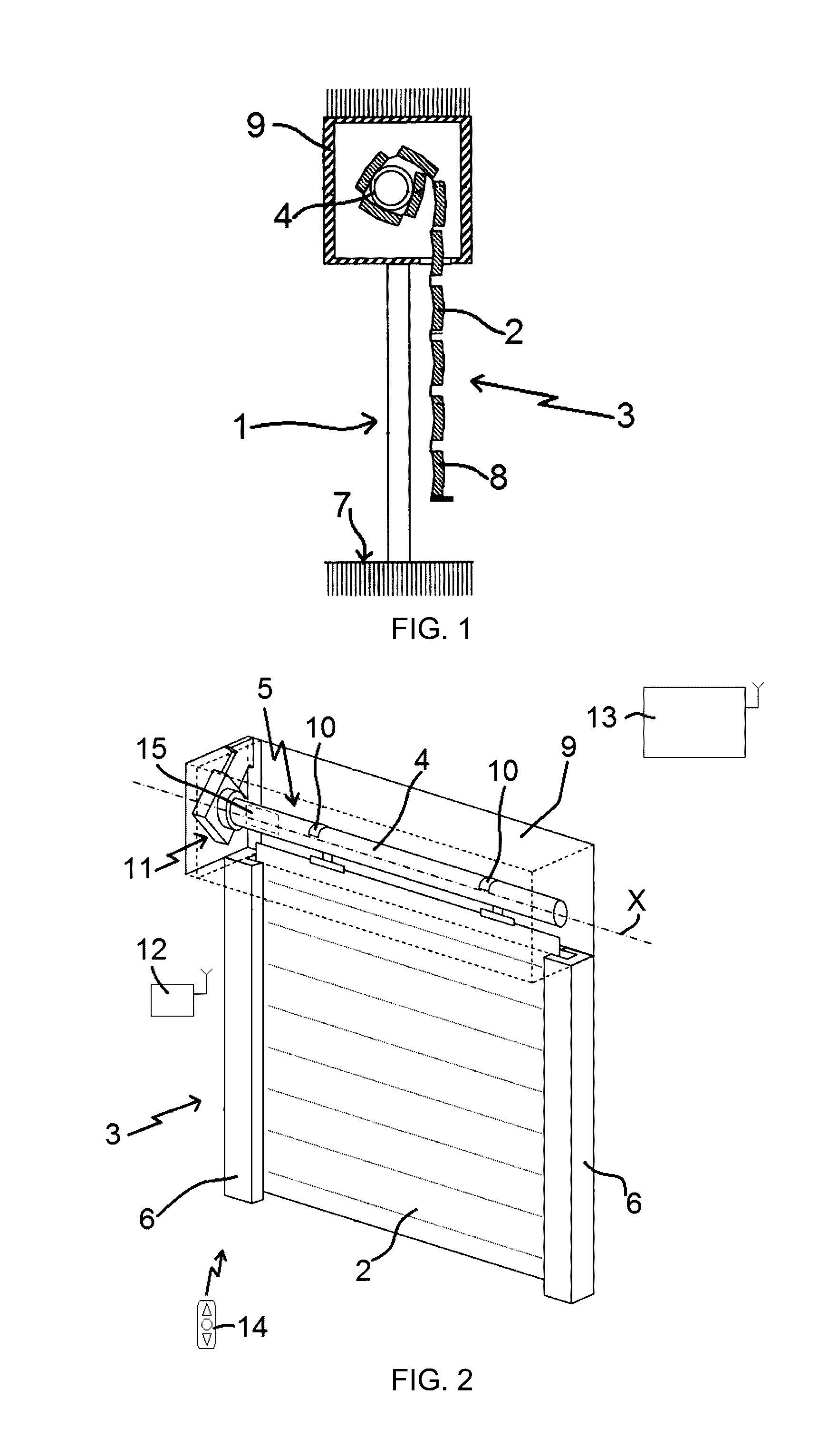
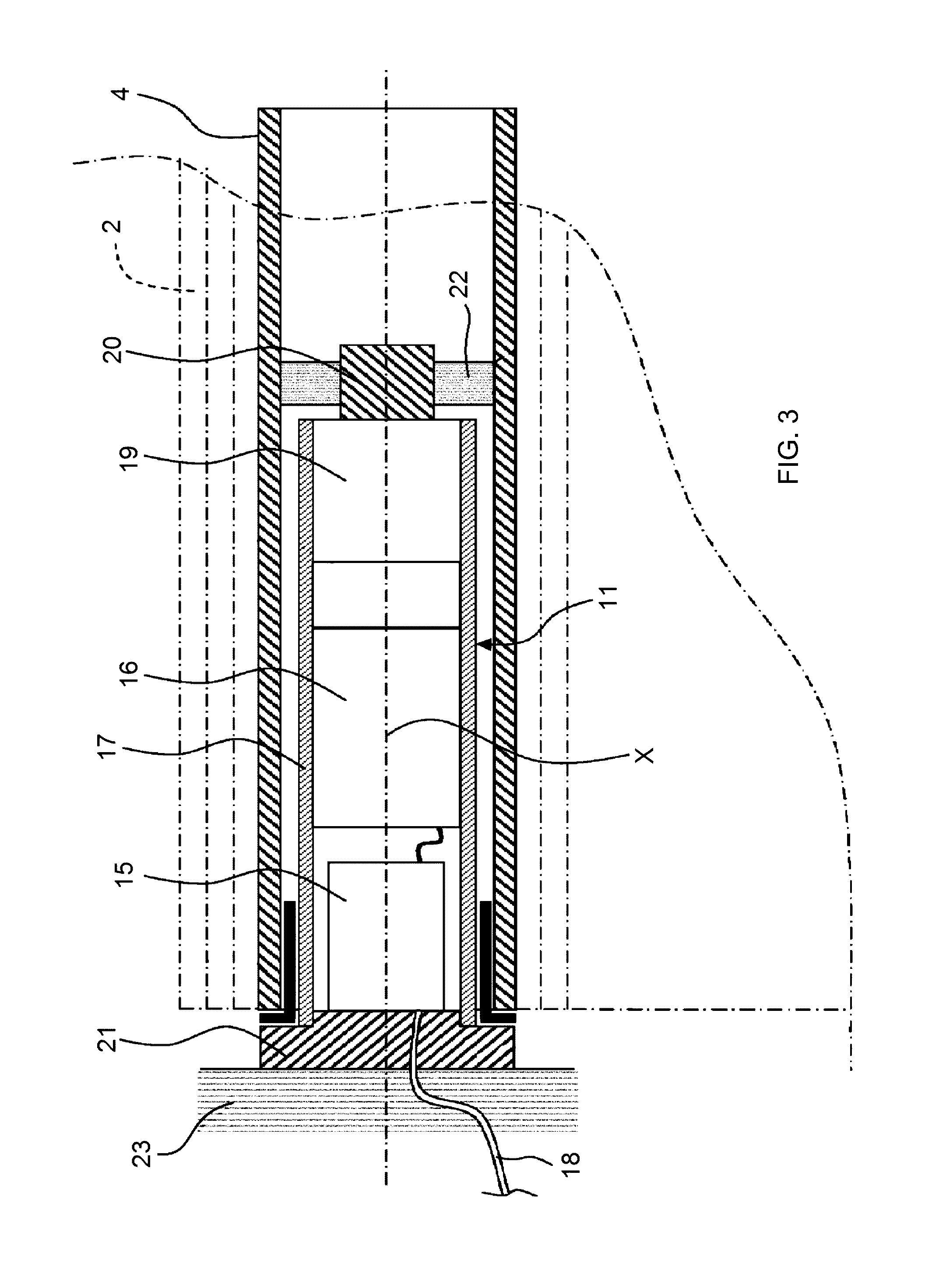
The present invention proposes an operating control method for a motorized driving device used in a closure or sun-protection home automation installation. The method aims to reduce electricity consumption and avoid depleting the battery by the electronic control unit. It achieves this by placing the control order receiving module of the electronic control unit in a standby state after the pairing of the control point with the electronic control unit and the activation of at least one selection element of the control point during a predetermined time period. This standby state reduces the electricity consumption and avoids depleting the battery, while making it possible to do away with an electronic control board at the autonomous electricity supply device and reducing cost and product quality risks.

Problems solved by technology

However, this motorized driving device has the drawback of adding an electronic control board to the autonomous power supply device including the switch positioned on the power supply line connecting the photovoltaic cell to the electromechanical actuator to inhibit the operation of the wireless control order receiving module, so as to limit the electricity consumption by the electronic control device and prevent draining the battery, between the assembly moment of the motorized driving device in the plant and the commissioning moment of the motorized driving device in the closure or sun-protection home automation installation.
Thus, the addition of this electronic control board including the switch creates an excess cost on the motorized driving device.

Method used


Image

  • Operating control method of a motorized driving device of a home automation installation
  • Operating control method of a motorized driving device of a home automation installation
  • Operating control method of a motorized driving device of a home automation installation

Examples


first embodiment

[0145]In reference to FIG. 5, we will now describe one embodiment of a method, according to the invention, for control, during operation, of the motorized driving device of a home automation installation illustrated in FIGS. 1 to 4.

[0146]In this embodiment, the operating control method of the motorized driving device 5 of the home automation installation comprises a step E10 for entering the configuration mode of the motorized driving device 5.

[0147]In one embodiment, the step E10 for entering the configuration mode of the motorized driving device 5 is carried out by simultaneously pressing on two selection elements of a control point 12, 14, in particular the remote control 14, for example the selection elements for raising and lowering the screen 2.

[0148]Furthermore, the simultaneous pressing on the two selection elements of the control point 12, 14 is carried out during at least one predetermined time period T1, which may be approximately one half-second.

[0149]In another embodime...

second embodiment

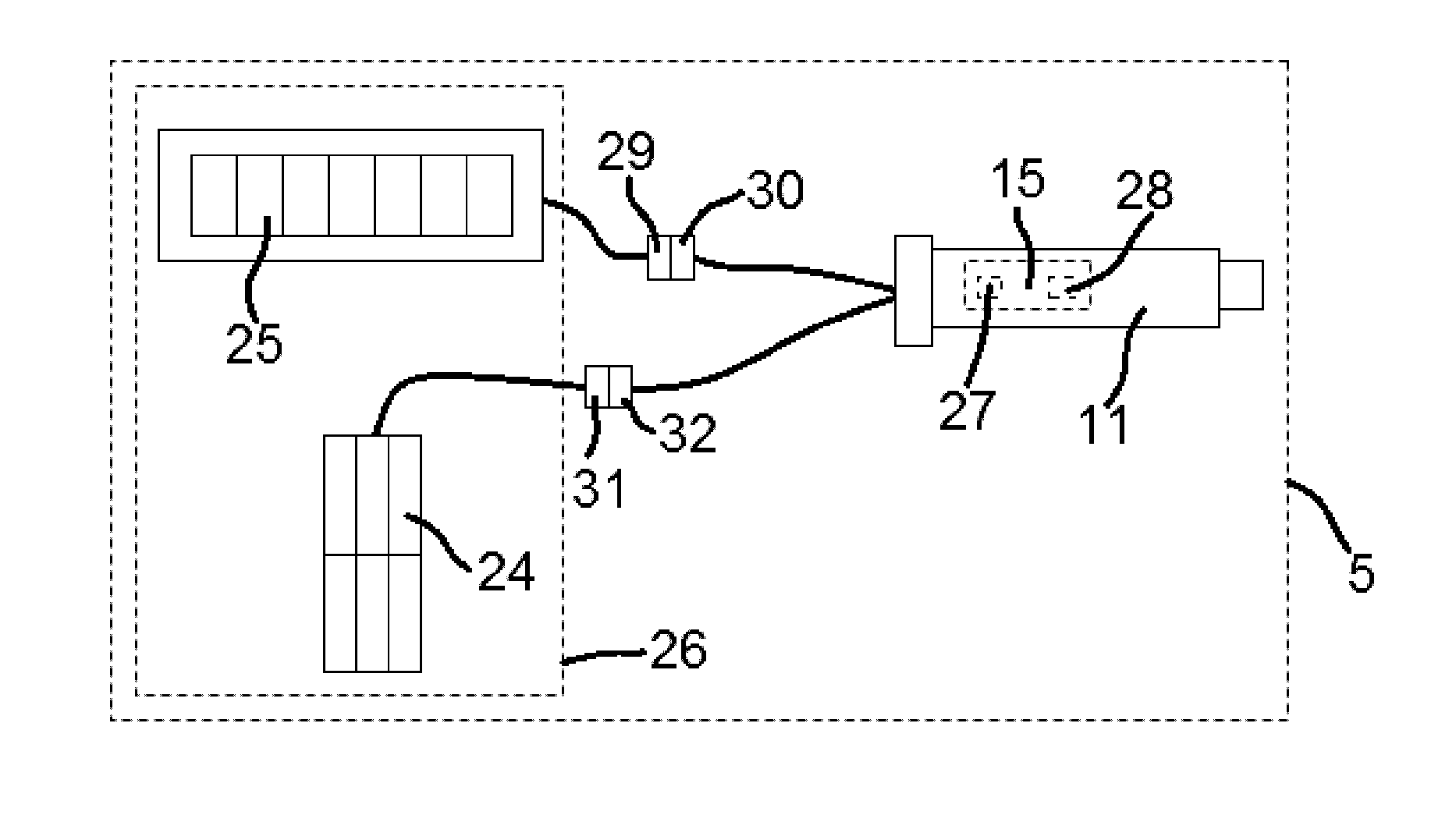
[0243]In this second embodiment, when the control order receiving module 27 of the electronic control unit 15 of the motorized driving device 5 is placed in the second standby state in step E80, the control method comprises a step E190, carried out after the measuring step E100 of the property G, for detecting supply and cutoff periods of the electricity supply of the electromechanical actuator 11 from the autonomous power supply device 26, only using measuring elements 28 for the property G related to the electricity supply of the electromechanical actuator 11 by the autonomous power supply device 26, a step E200 for simulating a sequence of supply and cutoff periods of the electricity supply of the electromechanical actuator 11, where the supply and cutoff periods of the electricity supply are detected through measuring elements 28, and the step E210 for exiting the second standby state of the control order receiving module 27 of the electronic control unit 15.

[0244]Thus, once the...


PUM


Abstract

An operating control method of a motorized driving device of a home automation installation comprises at least one step for entering a configuration mode of the device, a step for pairing a control point with an electronic control unit of the device, a step for activating at least one selection element of the control point during a predetermined time period beginning after the pairing step and a step for entering a second standby state of a control order receiving module of the electronic control unit. The second standby state of the control order receiving module has a wake-up frequency of the control order receiving module lower than the wake-up frequency of the control order receiving module in a first standby state.

Description

FIELD OF THE INVENTION[0001]The present invention relates to an operating control method of a motorized driving device of a closure or sun-protection home automation installation.[0002]In general, the present invention relates to the field of concealment devices comprising a motorized driving device setting a screen in motion between at least one first position and one second position.BACKGROUND OF THE INVENTION[0003]A motorized driving device comprises an electromechanical actuator for a movable element for closing, concealing or providing sun protection such as a shutter, door, gate, blind, or any other equivalent material, hereinafter referred to as a screen.[0004]Document FR 2,610,668 A1 is already known, and describes a motorized driving device for a closure or sun protection home automation installation comprising an electromechanical actuator, an electronic control unit and an autonomous power supply device. The autonomous power supply device comprises a battery and a photovo...

Claims


Application Information

Patent Timeline
Patent Type & Authority Applications(United States)
IPC IPC(8): E06B9/72E06B9/11
CPCE06B9/11E06B9/72E06B9/68E06B2009/2476E06B2009/6809G08C17/02G08C2201/12G08C2201/114
Inventor SCHNEIDER, THIERRYPAILLERET, GUILLAUMEJADOT, VINCENT
Owner SIMU
Learn More