Liquid crystal display panel

Inactive Publication Date: 2016-12-29
AU OPTRONICS CORP
View PDF5 Cites 5 Cited by
  • Summary
  • Abstract
  • Description
  • Claims
  • Application Information

AI Technical Summary

Benefits of technology

The invention is about a liquid crystal display panel that prevents light leaks and color mixing while still having a large aperture ratio. This is achieved by placing layers of color filters together with light-shielding patterns to prevent light from leaking through the edges and corners of the display. Overall, this improves the quality of the display and enhances its performance.

Problems solved by technology

However, the black matrix layers of the existing LCD panels affected by manufacturing processes, materials, or the like are likely to encounter the issue of corner rounding (as shown in FIG. 1), and thus the aperture ratio of the pixels is lowered down.

Method used


Image

  • Liquid crystal display panel
  • Liquid crystal display panel
  • Liquid crystal display panel

Examples


Embodiment Construction

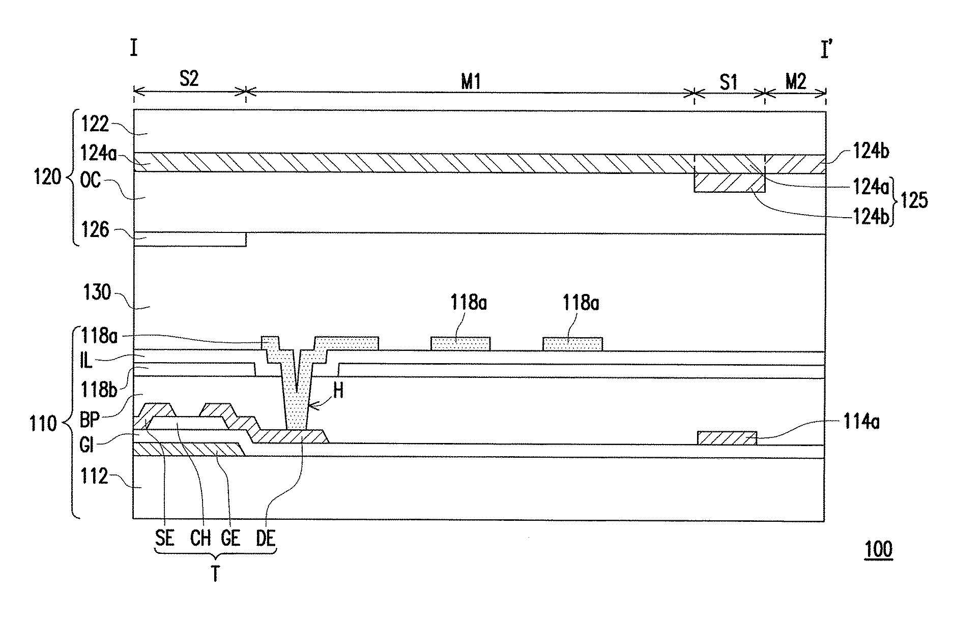
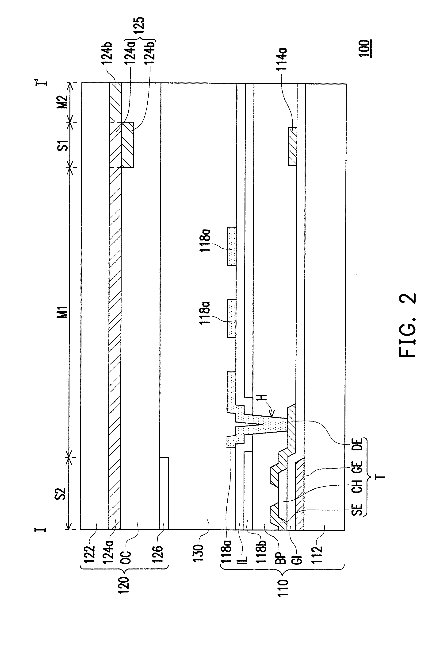
[0030]FIG. 2 is a schematic cross-sectional view illustrating an LCD panel according to an embodiment of the invention. FIG. 3 is a schematic top view illustrating a portion of the pixel array substrate depicted in FIG. 2. FIG. 4 is a schematic top view illustrating a portion of the color filter substrate depicted in FIG. 2. FIG. 5 is a schematic cross-sectional view taken along a sectional line A-A′ depicted in FIG. 4. FIG. 6 is a schematic cross-sectional view taken along a sectional line B-B′ depicted in FIG. 4. FIG. 7 is a schematic cross-sectional view taken along a sectional line C-C′ depicted in FIG. 4. Besides, the cross-sectional location depicted in FIG. 2 corresponds to the location of the sectional line I-I′ depicted in FIG. 3 and FIG. 4. An embodiment of the invention is provided hereinafter in detail with reference to FIG. 2, FIG. 3, FIG. 4, FIG. 5, FIG. 6, and FIG. 7.

[0031]With reference to FIG. 2, an LCD panel 100 includes a pixel array substrate 110, a color filter ...


PUM


Abstract

An LCD panel includes first and second substrates, signal lines, pixel structures, first, second, and third color filter pattern layers, a light-shielding pattern layer, and a liquid crystal medium. The second substrate has first and second light-shielding regions and first, second and third light-transmissive regions. The first and second light-shielding regions define the first, second and third light-transmissive regions. The first color filter pattern layer is correspondingly located in the first light-transmissive regions and the first light-shielding regions. The second color filter pattern layer is correspondingly located in the second light-transmissive regions and the first light-shielding regions. The first and second color filter pattern layers are stacked together in the first light-shielding regions. The third color filter pattern layer is correspondingly located in the third light-transmissive regions. The light-shielding patterned layer is correspondingly located in the second light-shielding regions and on the first, second, and third color filter pattern layers.

Description

CROSS-REFERENCE TO RELATED APPLICATION[0001]This application claims the priority benefit of Taiwan application serial no. 104120976, filed on Jun. 29, 2015. The entirety of the above-mentioned patent application is hereby incorporated by reference herein and made a part of this specification.FIELD OF THE INVENTION[0002]The invention relates to a display panel and in particular to a liquid crystal display (LCD) panel.DESCRIPTION OF RELATED ART[0003]As the development of liquid crystal display (LCD) panels advances, high resolution has become one of the basic requirements. In the existing LCD panels, the high-resolution requirement is often satisfied by reducing the dimension of pixels. However, the black matrix layers of the existing LCD panels affected by manufacturing processes, materials, or the like are likely to encounter the issue of corner rounding (as shown in FIG. 1), and thus the aperture ratio of the pixels is lowered down. In order to comply with the high-resolution requi...

Claims


Application Information

Patent Timeline
IPC IPC(8): G02F1/1335G02F1/1343G02F1/1362G02F1/1368
CPCG02F1/133512G02F1/1368G02F2001/133357G02F1/136286G02F1/133514G02F1/134309G02F1/133509G02F2201/40
Inventor YEH, PI-CHUNCHENG, CHING-SHENG
Owner AU OPTRONICS CORP
Why Eureka
Try Eureka