Display control system for vehicle

Inactive Publication Date: 2016-12-29
TOYOTA JIDOSHA KK
View PDF1 Cites 7 Cited by
  • Summary
  • Abstract
  • Description
  • Claims
  • Application Information

AI Technical Summary

Benefits of technology

[0019]In the display control system as described above, the electronic control unit may be configured to set a gain such that the gain when the vehicle acceleration is low is larger than the gain when the vehicle acceleration is high, to make the display of the vehicle acceleration be more likely to change as the vehicle acceleration is lower. With this arrangement, in a regular operation region of the vehicle, the sensitivity or response of display of the vehicle acceleration to change thereof is increased, and even a small change i

Problems solved by technology

It has been proposed to display the distribution of the driving force among wheels during traveling, and inform the driver of a condition of distribution of the driving force as needed, as described in JP 2011-0466362 A. However, the display does not enable the driver to intuitively grasp the relationship between the distribution of the driving force and a

Method used


Image

  • Display control system for vehicle
  • Display control system for vehicle
  • Display control system for vehicle

Examples


first embodiment

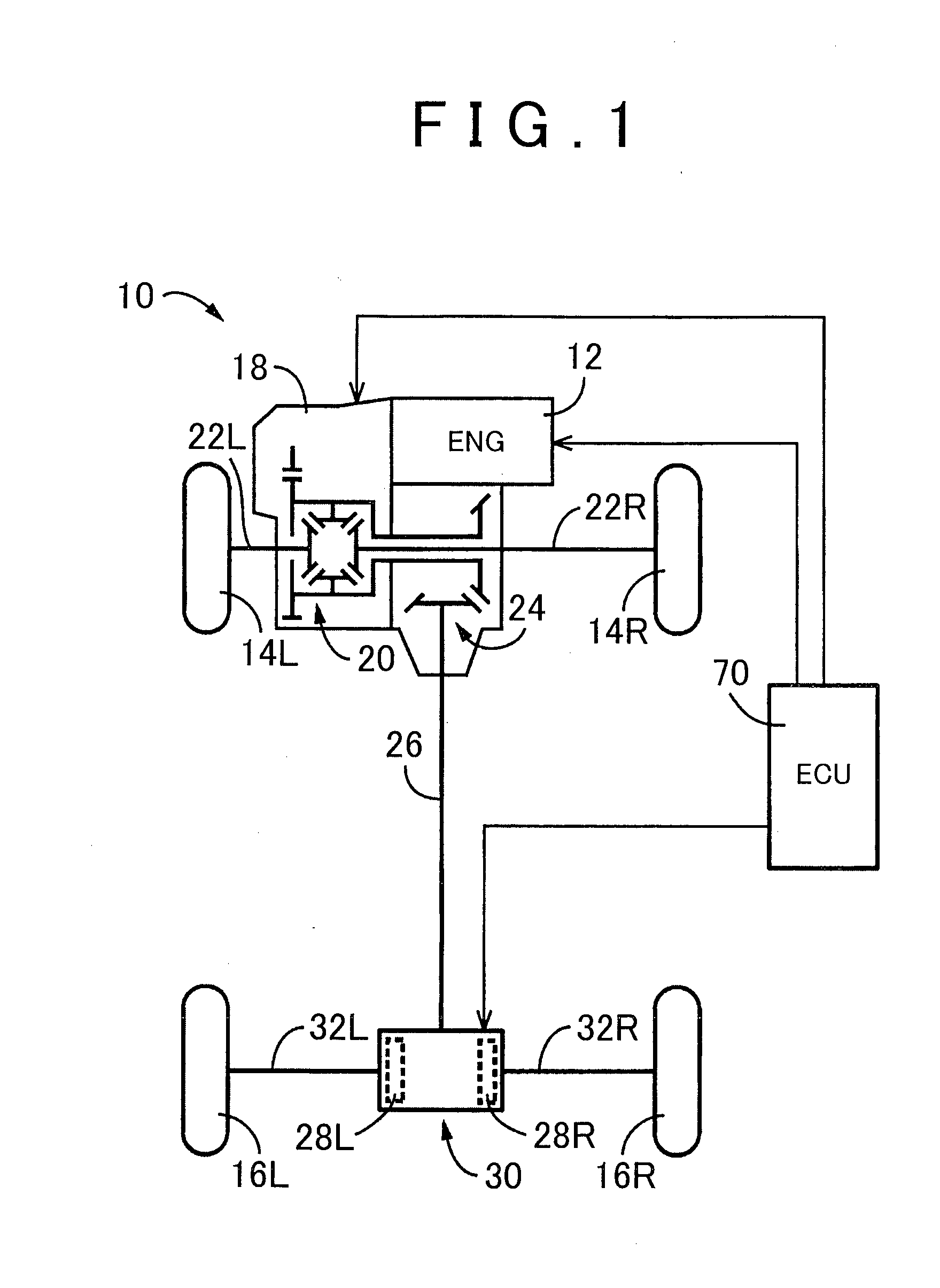
[0049]FIG. 3 shows one example of the mimic vehicle diagram 64 according to the invention. In the mimic vehicle diagram 64 of FIG. 3, which is a perspective view, the vehicle 10 as seen from diagonally behind is drawn in perspective. More specifically, an engine 70 on display (corresponding to the engine 12), transmission 72 on display (corresponding to the transmission 18), transfer 74 on display (corresponding to the transfer 24), propeller shaft 76 on display (corresponding to the propeller shaft 26), right-left-wheel driving force distribution mechanism 78 on display (corresponding to the right-left-wheel driving force distribution mechanism 30), front-wheel axles 80R, 80L on display (corresponding to the front-wheel axles 22), rear-wheel axles 82R, 82L on display (corresponding to the rear-wheel axles 32), right and left front wheels 84R, 84L on display (corresponding to the right and left front wheels 14), and right and left rear wheels 86R, 86L on display (corresponding to th...

second embodiment

[0069]FIG. 8 shows one example of mimic vehicle diagram 100 according to the invention. In the mimic vehicle diagram 100 of FIG. 8, a center 104 of a plurality of concentric circles 102 indicating the vehicle acceleration G is set in the vicinity of the seated position of the driver. With the center 104 of the concentric circles 102 thus set to this position, the vehicle acceleration G is displayed with respect to the center located at the position of the driver in the mimic vehicle diagram 100. Accordingly, the driver can sensually grasp the vehicle acceleration G with further ease.

[0070]As described above, this embodiment provides the same effects as those of the above-described embodiment, and also provides an effect of enabling the driver to sensually grasp the vehicle acceleration G with further ease, by setting the center 104 of the concentric circles 102 in the vicinity of the seated position of the driver.

third embodiment

[0071]FIG. 9 shows one example of mimic vehicle diagram 110 according to the invention. In the mimic vehicle diagram 110 of FIG. 9, the vehicle acceleration G is indicated by an arrow 114, in place of the ball 90 that indicates the magnitude and direction of the vehicle acceleration G in the mimic vehicle diagram 64 shown in FIG. 3. The arrow 114 shown in FIG. 9 has a base located at the center of concentric circles 112, and its distal end points in a direction in which the vehicle acceleration G is applied. Also, the length of the arrow 114 indicates the magnitude of the vehicle acceleration G, and the magnitude of the vehicle acceleration G increases as the length of the arrow 114 increases. Thus, the direction and magnitude of the vehicle acceleration G may be indicated by use of the arrow 114. If an abnormality occurs to detection of the vehicle acceleration G, a light illuminating the arrow may be turned off or caused to blink, for example, so as to inform the driver of the occ...


PUM


Abstract

The invention relates to a display control system including a display installed inside the vehicle. The driving force of wheels (84L, 84R, 86L, 86R) are calculated as needed, and magnitude and a direction of the vehicle acceleration (90, 90′) which change according to the driving force are displayed at the same time on a mimic vehicle diagram (70-86) displayed on the in-vehicle display. Thus, the driver can grasp the relationship between the driving force of each wheel (84L, 84R, 86L, 86R), and the magnitude and the direction of the vehicle acceleration (90, 90′). Accordingly, the driver can drive the vehicle in view of the relationship between the driving force of the wheels (84L, 84R, 86L, 86R), and the magnitude and direction of the vehicle acceleration (90, 90′).

Description

BACKGROUND OF THE INVENTION[0001]1. Field of the Invention[0002]The invention relates to a display control system for a vehicle, and in particular to a display control system that displays traveling conditions of the vehicle, using a mimic vehicle diagram displayed on an in-vehicle display.[0003]2. Description of Related Art[0004]A display system that displays traveling conditions of a vehicle, using a mimic vehicle diagram displayed on an in-vehicle display, is known. A torque display system for a vehicle as described in Japanese Patent Application Publication No. 2011-046362 (JP 2011-046362 A) is one example of the above type of display system. In the system of JP 2011-046362 A, the driving force of each drive wheel on the mimic vehicle diagram is indicated by a plurality of segments. As another example of display system, it has been proposed to display the vehicle acceleration or the steering angle alone.SUMMARY OF THE INVENTION[0005]It has been proposed to display the distributi...

Claims


Application Information

Patent Timeline
IPC IPC(8): G06T11/20G09G5/00B60K35/00
CPCG06T11/206B60K35/00G09G5/003G06T11/001B60K2350/203B60K2350/962G06T3/40B60K2350/1096B60K23/0808B60K2023/043B60W2050/146B60W2520/105B60W2520/125B60W2520/30B60W2520/403B60W2520/406B60W2540/18B60T2270/411B62D15/02B60K2370/167B60K2370/33B60K2370/186B60K2370/1868
Inventor FUKADA, SHUNROSHIMIZU, SATOSHI
Owner TOYOTA JIDOSHA KK
Why Eureka
Try Eureka