Antenna system for interference supression

a technology of interference supression and antenna system, which is applied in the direction of antennas, antenna details, electrical equipment, etc., can solve the problems of increasing the volume required to integrate multiple antennas in a wireless device, prohibiting the effective implementation of such complex antenna arrays, and increasing the amount of unwanted signals. , to achieve the effect of improving the signal to noise ratio (snr) performance, increasing the intended signal, and reducing undesirable signals

Active Publication Date: 2013-05-30
KYOCERA AVX COMPONENTS (SAN DIEGO) INC
View PDF0 Cites 16 Cited by
  • Summary
  • Abstract
  • Description
  • Claims
  • Application Information

AI Technical Summary

Benefits of technology

[0011]In various embodiments, an active tunable antenna is capable of active beam adjustment, configuring the antenna radiation pattern for providing gain maxima in the direction of intended communication and gain minima in the direction of one or multiple interferers. This active tuning is adapted to result in link budget improvement by increasing the intended signal and decreasing the undesirable signals, providing improved signal to noise ratio (SNR) performance.

Problems solved by technology

But effective implementation of such complex antenna arrays may be prohibitive due to size constraints associated with mobile devices.
Additionally, it is cost prohibitive in many applications to provide multiple power amplifiers or the feed network required to excite multiple antennas.
The difficulty of this approach is the volume required to integrate multiple antennas in a wireless device along with the complexity of designing and implementing a feed network to distribute the RF signals to multiple antenna elements.

Method used


Image

  • Antenna system for interference supression
  • Antenna system for interference supression
  • Antenna system for interference supression

Examples


Embodiment Construction

[0029]In the following description, for purposes of explanation and not limitation, details and descriptions are set forth in order to provide a thorough understanding of the present invention. However, it will be apparent to those skilled in the art that the present invention may be practiced in other embodiments that depart from these details and descriptions.

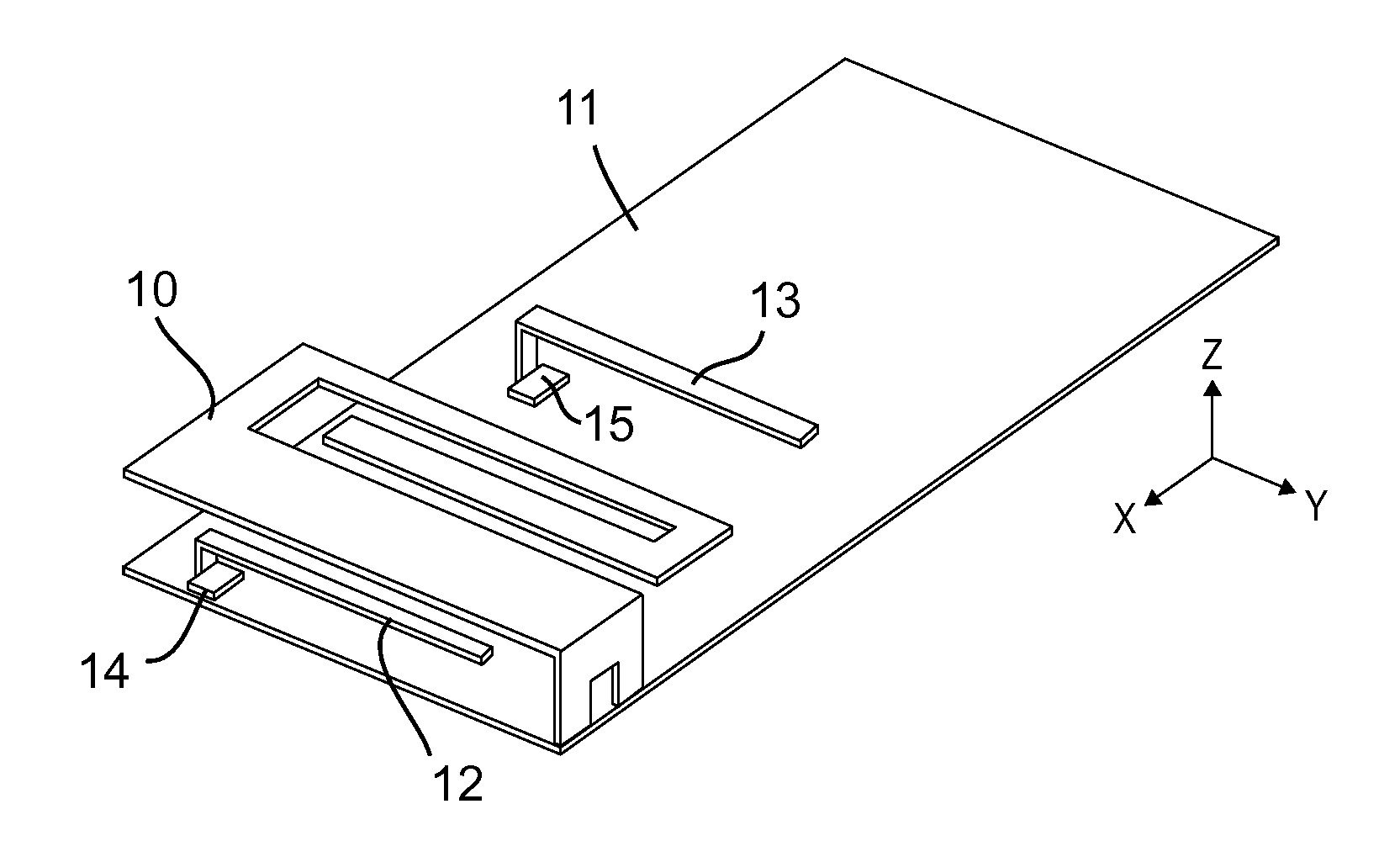
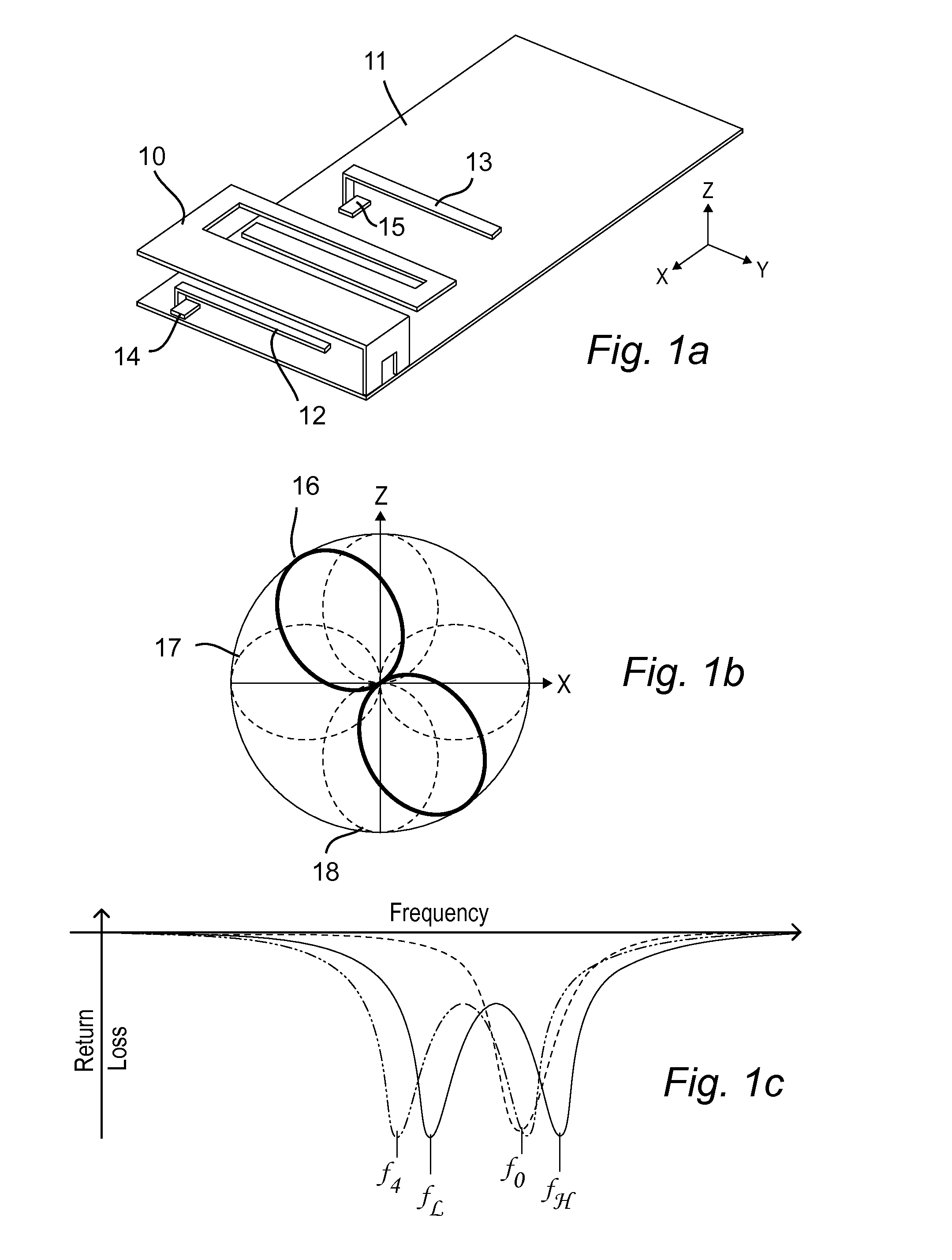
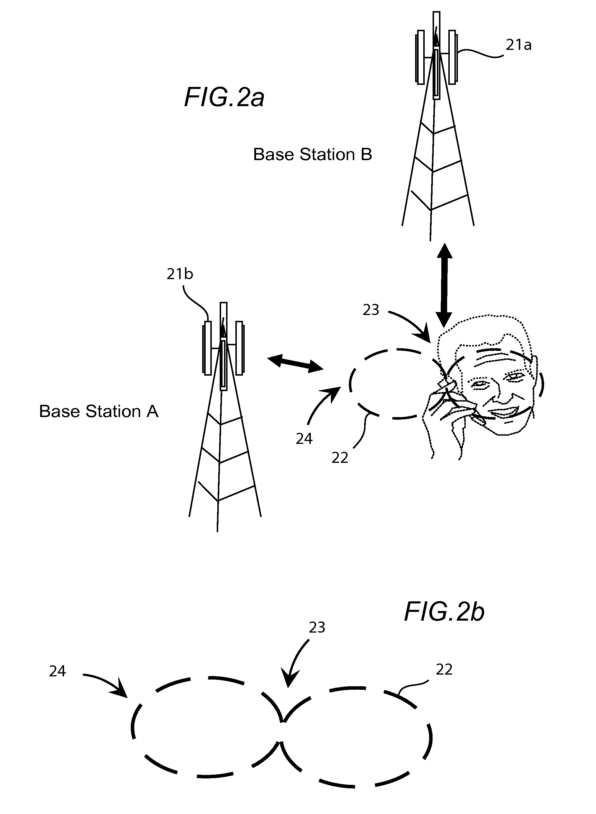
[0030]The antenna systems described herein utilize a beam steering technique to reduce interference from one or multiple sources. A platform has been derived to increase the link budget based on the modification of the antenna radiation pattern and is, in part, based upon U.S. Ser. No. 12 / 043,090, filed Mar. 5, 2008, titled “ANTENNA AND METHOD FOR STEERING ANTENNA BEAM DIRECTION”, which issued as U.S. Pat. No. 7,911,402 on Mar. 22, 2011, hereinafter “the '402 patent”; the contents of which are hereby incorporated by reference. The '402 patent describes a structure capable of modifying an antenna radiation pattern, which in th...


PUM


Abstract

An antenna system is capable of optimizing communication link quality with one or multiple transceivers while suppressing one or multiple interference sources. The antenna provides a low cost, physically small multi-element antenna system capable of being integrated into mobile devices and designed to form nulls in the radiation pattern to reduce interference from unwanted interferers. The antenna system operates in both line of sight and high multi-path environments by adjusting the radiation pattern and sampling the received signal strength to reduce signal levels from interferers while monitoring and optimizing receive signal strength from desired sources.

Description

CROSS-REFERENCE TO RELATED APPLICATIONS[0001]This application is a continuation-in-part (CIP) of commonly owned U.S. Ser. No. 13 / 029,564, filed Feb. 17, 2011, titled “ANTENNA AND METHOD FOR STEERING ANTENNA BEAM DIRECTION”; which in turn claims priority to[0002]U.S. Ser. No. 12 / 043,090, filed Mar. 5, 2008, titled “ANTENNA AND METHOD FOR STEERING ANTENNA BEAM DIRECTION”, issued as U.S. Pat. No. 7,911,402 on Mar. 22, 2011; the contents of each of which are hereby incorporated by reference.BACKGROUND OF THE INVENTION[0003]1. Field of the Invention[0004]This invention relates generally to the field of wireless communication. In particular, this invention relates to antenna systems and methods for optimizing communication link quality with intended transceivers.[0005]2. Description of the Related Art[0006]As new generations of handsets, gateways, and other wireless communication devices become embedded with more applications and the need for bandwidth becomes greater, new antenna systems...

Claims


Application Information

Patent Timeline
Patent Type & Authority Applications(United States)
IPC IPC(8): H01Q9/06
CPCH01Q9/06H01Q9/0421H01Q3/00H01Q1/243H01Q19/005
Inventor SHAMBLIN, JEFFREYROWSON, SEBASTIANDESCLOS, LAURENT
Owner KYOCERA AVX COMPONENTS (SAN DIEGO) INC
Why Eureka
Try Eureka