Sliding door for a metal wired pet cage

Active Publication Date: 2017-01-05
JIANGSU ZHONGHENG PET ARTICLES JOINT CO LTD
View PDF0 Cites 11 Cited by
  • Summary
  • Abstract
  • Description
  • Claims
  • Application Information

AI Technical Summary

Benefits of technology

[0017]5) The articulation part between the lifting handle and the sliding-type door plate is of a circular arc, and the circular arc pa

Problems solved by technology

A technical problem to be solved by embodiments of the present invention is that: the existing sliding door of the metal wired cage is inconvenient to operate, and is relatively laborious to operate esp

Method used


Image

  • Sliding door for a metal wired pet cage
  • Sliding door for a metal wired pet cage
  • Sliding door for a metal wired pet cage

Examples


Example

[0025]In FIGs., the references are as follows: the torsional springs 1, the locking member 2, the lifting handle 3, the square guide rails 4, the circular guide rails 5, the sliding type door plate 6, and the articulation part 3a between the lifting handle and the sliding type door plate are marked.

DETAILED DESCRIPTIONS OF THE PREFERRED EMBODIMENTS

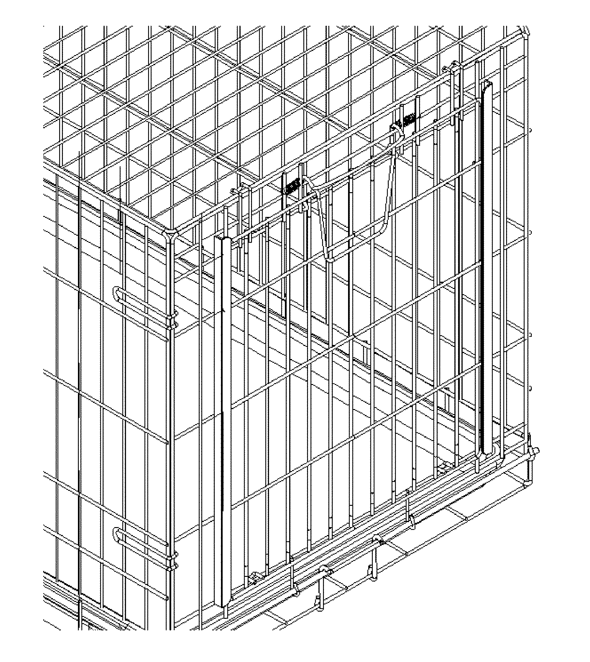
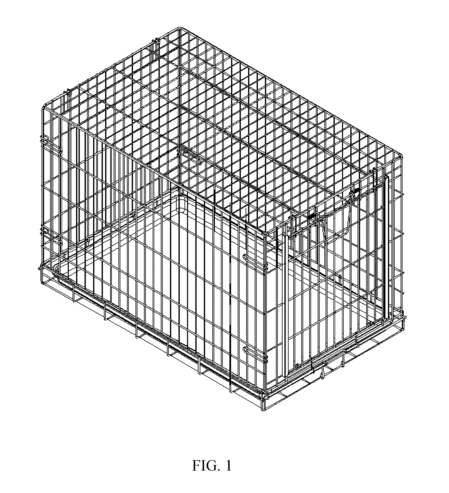
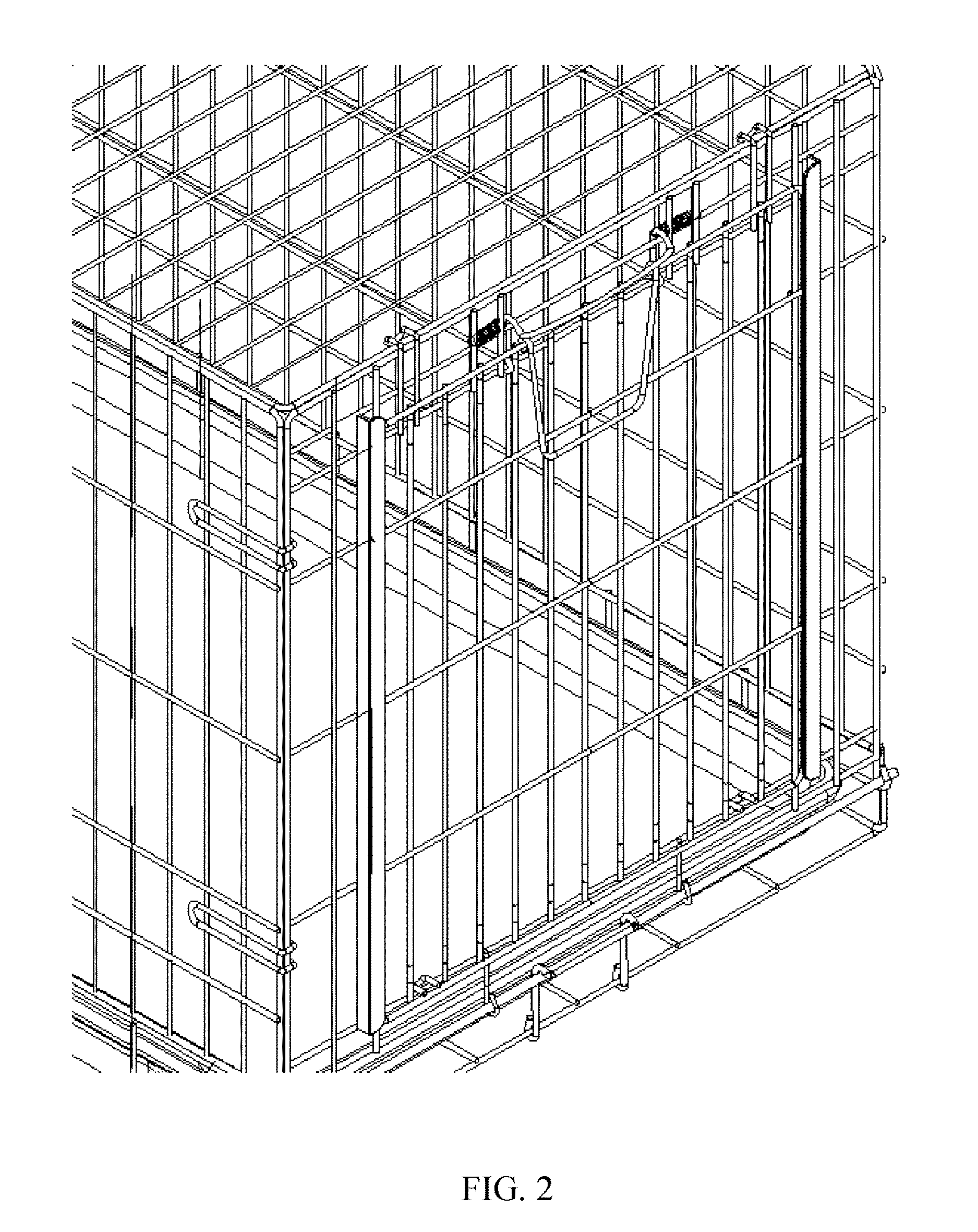
[0026]With reference to FIG. 1 to FIG. 7, in accordance with embodiments of the invention, a siding door for an metal wired pet cage may comprise a pair of torsional springs 1, a rotary locking member 2, a rotary lifting handle 3, and a sliding-type door plate 6. Sliding guide rails of the sliding door may be configured longitudinally. The lifting handle 3 is hinged and fixed to the upper end of the sliding-type door plate 6. A pair of torsional springs 1 are fixed on the pet cage and are connected with both ends of the locking member 2. The torsional springs 1 is configured to drive the locking member 2 to prop against the lifting handle ...


PUM


Abstract

A sliding door for a metal wired pet cage includes a pair of torsional springs; a rotary locking member; a rotary lifting handle; and a sliding-type door plate; wherein sliding guide rails of the sliding door are configured longitudinally, wherein the lifting handle is hingedly fixed to an upper end of the sliding-type door plate, the pair of torsional springs are fixed on the metal wired pet cage and are connected with both ends of the locking member, and the torsional springs is configured to drive the locking member to prop against the lifting handle so that the sliding-type door plate is at a locking state. When the sliding type door plate needs to be opened, the lifting handle is rotated upwards so that the locking member is separated from the lifting handle, and the lifting handle drives the sliding-type door plate to move upwards along the sliding guide rails.

Description

CROSS-REFERENCE TO RELATED APPLICATIONS[0001]This Application claims the priority of Chinese Patent Application No. 201520461838, filed on Jun. 30, 2015, the disclosure of which is incorporated by reference in its entirety.TECHNICAL FIELD[0002]The present invention relates to a pet cage, in particular to a sliding door for a metal wired pet cage, belonging to the technical field of pet cages.BACKGROUND ART[0003]In the existing metal wired mesh cages for keeping pets, a door capable of being opened and closed is disposed on one side of a cage, and the door is generally of a rotating type or a sliding type. Whether it is a rotating type or a sliding type, the door is generally locked via a bolt. During use, the bolt is capable of being moved left and right, or up and down, in manual operations. Such bolts are inconvenient to operate and are relatively laborious to operate especially when the metal wired mesh cage is rusted or insufficiently lubricated. In addition, as an independent p...

Claims


Application Information

Patent Timeline
IPC IPC(8): A01K1/03A01K1/02E05D15/16E05B65/08E05C3/16
CPCA01K1/03E05B65/08A01K1/0245E05D15/165E05C3/16A01K31/02A01K31/06E05B2015/1692E05C3/02
Inventor BIN, QIU
Owner JIANGSU ZHONGHENG PET ARTICLES JOINT CO LTD
Why Eureka
Try Eureka