Optical coherence tomography (OCT) system with improved motion contrast

a coherence tomography and optical coherence technology, applied in the field of optical coherence tomography, can solve the problems of limited technique, slowest motions become obscured by noise, and current oct technology may not provide adequate visualization of retinal and choroidal microvasculature, so as to reduce the effect of at least one noisy b-scan cluster and one or more noisy data effects

Active Publication Date: 2017-01-05
UNIV OF SOUTHERN CALIFORNIA +1
View PDF1 Cites 13 Cited by
  • Summary
  • Abstract
  • Description
  • Claims
  • Application Information

AI Technical Summary

Benefits of technology

[0037]The OCT system may have a configuration that uses the weighting method and wherein the weighting method includes reducing effects of at least one noisy B-scan cluster by using a weighting criterion.
[0038]The OCT system may have a configuration that uses the weighting met

Problems solved by technology

However, despite the rapid evolution of OCT imaging, current OCT technology may not provide adequate visualization of retinal and choroidal microvasculature.
Doppler OCT has been used to image large axial flow in the retina, but without dedicated scanning protocols this technique is limited in cases of slow flow or flow oriented transverse to the imaging

Method used


Image

  • Optical coherence tomography (OCT) system with improved motion contrast
  • Optical coherence tomography (OCT) system with improved motion contrast
  • Optical coherence tomography (OCT) system with improved motion contrast

Examples


example 1

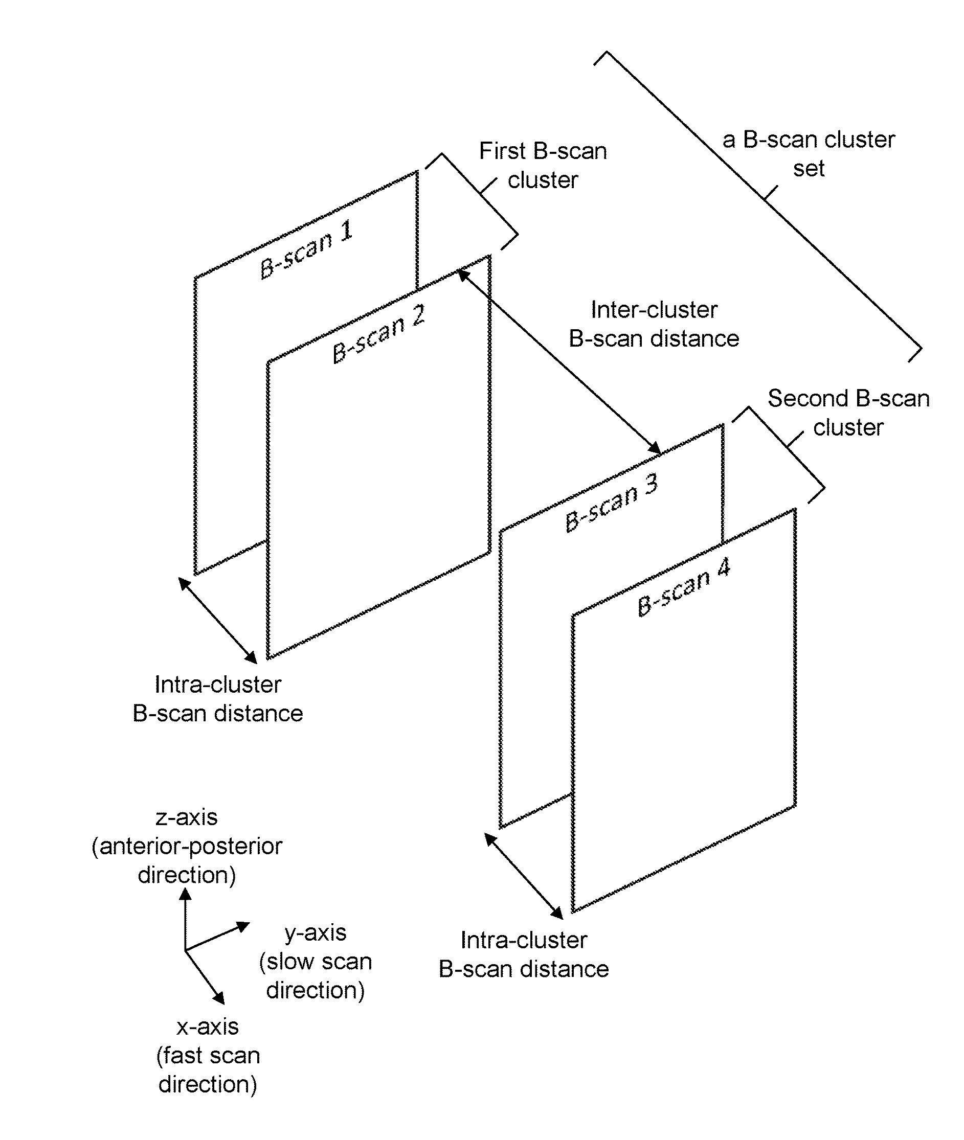
Using a B-Scan Cluster Set Comprising Two B-Scan Clusters to Enhance OCT Motion Contrast

[0106]In this example, PV-OCT method is used as the OCT motion contrast method. The phase difference between B-scans is used to calculate the statistical variance for the motion contrast. The data is acquired from two neighboring B-scan clusters, each comprising 4 B-scans. That is, there are two B-scan clusters within each B-scan cluster. Three phase changes are calculated for each B-scan cluster, with a total of 6 phase changes for the B-scan cluster set. The phase variance thus calculated is assigned to one of the neighboring pairs of the B-scans.

[0107]Typical methods would only calculate contrast from within each B-scan cluster. To achieve the same number of statistics of 6 phase changes would require 7 B-scans for each B-scan cluster, in comparison to the 4 B-scans required in this example.

[0108]Exemplary OCT images of a retinal vasculature formed by using the OCT motion contrast method discl...

example 2

Using One Complete B-Scan Cluster of Data and a Fraction of the Data from a Neighboring Cluster

[0110]In this example, PV-OCT method is used as the OCT motion contrast method. The phase difference between B-scans is used to calculate the statistical variance for image contrast. The data is acquired to form two neighboring B-scan clusters, each comprising 4 B-scans. Three phase changes are calculated for one B-scan cluster and two phase changes are calculated for the other B-scan cluster. Thus, there are a total of 5 phase changes for the B-scan cluster set. The phase variance thus calculated is assigned to one of the neighboring pairs of the B-scans.

[0111]In this example, not all B-scans in each cluster are used in the phase change calculations, although they are acquired for each cluster. This exemplary method reduces calculation time for the phase variance by a factor of 6 / 5 as compared to that disclosed in Example 1.

[0112]Thus, the imaging speed may further be increased by using e...

example 3

[0113]In this example, the intensity variance is calculated to form an OCT image. Typical intensity variance imaging methods may require a minimum of 4 B-scans in each B-scan cluster to perform 3 phase change calculations.

[0114]However, in the OCT motion contrast method, a B-scan cluster set comprising two B-scan clusters comprising three B-scans per B-scan cluster may provide similar OCT motion contrast as follows. In this example, since each B-scan cluster provides 2 phase change calculations, there are total of 4 phase change calculations available for outlier analysis and motion contrast calculations. Thus, the required number of B-scans per cluster may be reduced from 4 to 3 by using the OCT motion contrast method disclosed above.


PUM


Abstract

This disclosure relates to the field of Optical Coherence Tomography (OCT). This disclosure particularly relates to an OCT system with improved motion contrast. This disclosure particularly relates to motion contrast methods for such OCT systems. The OCT system of this disclosure may have a configuration that scans a physical object, which has a surface and a depth, with a beam of light that has a beam width and a direction; acquires OCT signals from the scan; forms at least one A-scan using the acquired OCT signals; forms at least one B-scan cluster set using the acquired OCT signals that includes at least two B-scan clusters that each include at least two B-scans. The B-scans within each B-scan cluster set are parallel to one another and parallel to the direction of the beam of light. The OCT system may have a configuration that calculates OCT motion contrast using the at least one B-scan cluster set. This OCT system may form and display an image of the physical object.

Description

CROSS-REFERENCE TO RELATED APPLICATION[0001]This application is based upon and claims priority to U.S. provisional patent application 61 / 935,428, entitled “OCT Angiography Enhanced Processing Techniques,” filed Feb. 4, 2014, attorney docket number CIT-6799-P. The entire content of this provisional patent application is incorporated herein by reference.STATEMENT REGARDING FEDERALLY SPONSORED RESEARCH[0002]This invention was made with government support under Grant No. NIH STTR 1 R41 EY021054 awarded by National Institutes of Health (NIH). The government has certain rights in the invention.BACKGROUND[0003]Technical Field[0004]This disclosure relates to the field of Optical Coherence Tomography (OCT). This disclosure particularly relates to an OCT system with improved motion contrast. This disclosure particularly relates to motion contrast methods for such OCT systems.[0005]Description of Related Art[0006]Optical coherence tomography (OCT) has become an indispensable clinical imaging t...

Claims


Application Information

Patent Timeline
IPC IPC(8): A61B3/00A61B3/12A61B5/00A61B3/10
CPCA61B3/0025A61B3/102A61B3/0041A61B5/7203A61B3/1233G01B9/02076G01B9/02091G01B2290/65
Inventor FINGLER, JEFFREY P.FRASER, SCOTT E.
Owner UNIV OF SOUTHERN CALIFORNIA
Why Eureka
Try Eureka