
Piezoelectric device, liquid ejection head, and method of manufacturing piezoelectric device

Active Publication Date: 2017-01-05
SEIKO EPSON CORP
View PDF2 Cites 0 Cited by
  • Summary
  • Abstract
  • Description
  • Claims
  • Application Information

AI Technical Summary

Benefits of technology

This patent describes a way to make a piezoelectric device that reduces the chance of the device breaking down. It does this by preventing the separation of two parts that make up the device. This makes the device more reliable and trustworthy. Overall, this patent explains how to make a better piezoelectric device that is easier to use and more reliable.

Problems solved by technology

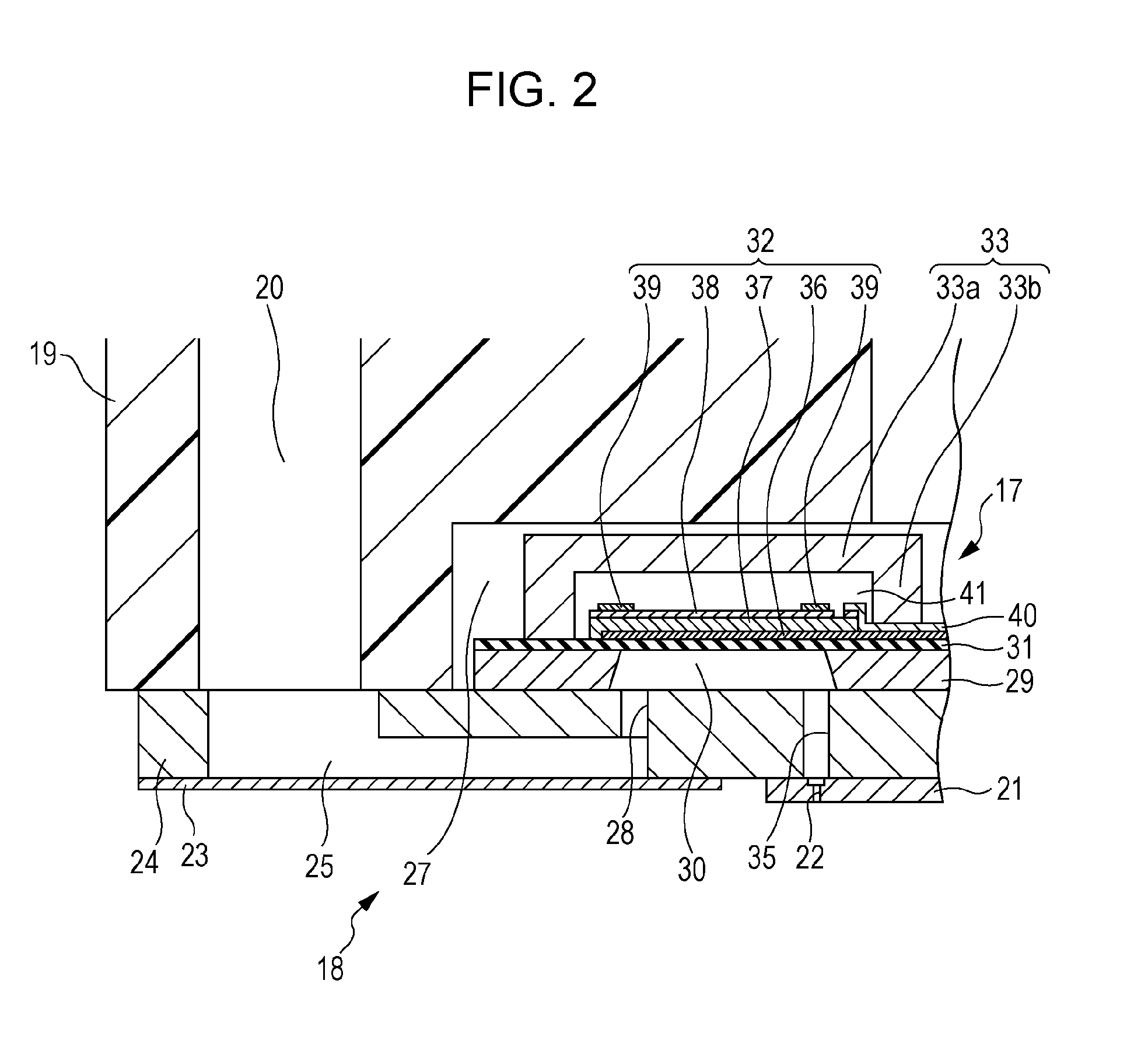
This decreased stiffness enables the pressure chamber-formed substrate to be readily deformed and may cause separation of the pressure chamber-formed substrate and the communication substrate that is bonded to the substrate.
Such a problem may similarly occur in other piezoelectric devices that include a first substrate formed by providing a piezoelectric element above an empty chamber and a second substrate that is bonded to the first substrate.

Method used


Image

  • Piezoelectric device, liquid ejection head, and method of manufacturing piezoelectric device
  • Piezoelectric device, liquid ejection head, and method of manufacturing piezoelectric device
  • Piezoelectric device, liquid ejection head, and method of manufacturing piezoelectric device

Examples


Embodiment Construction

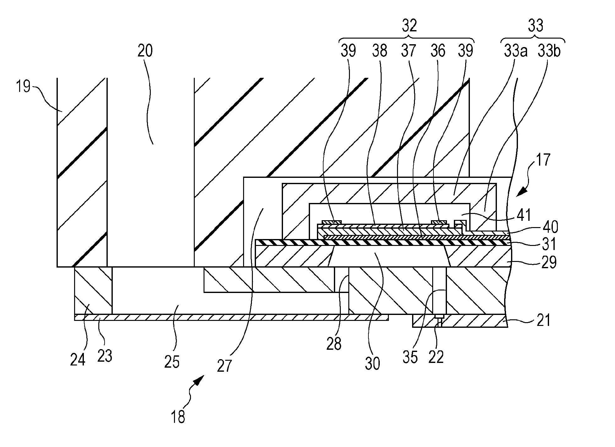
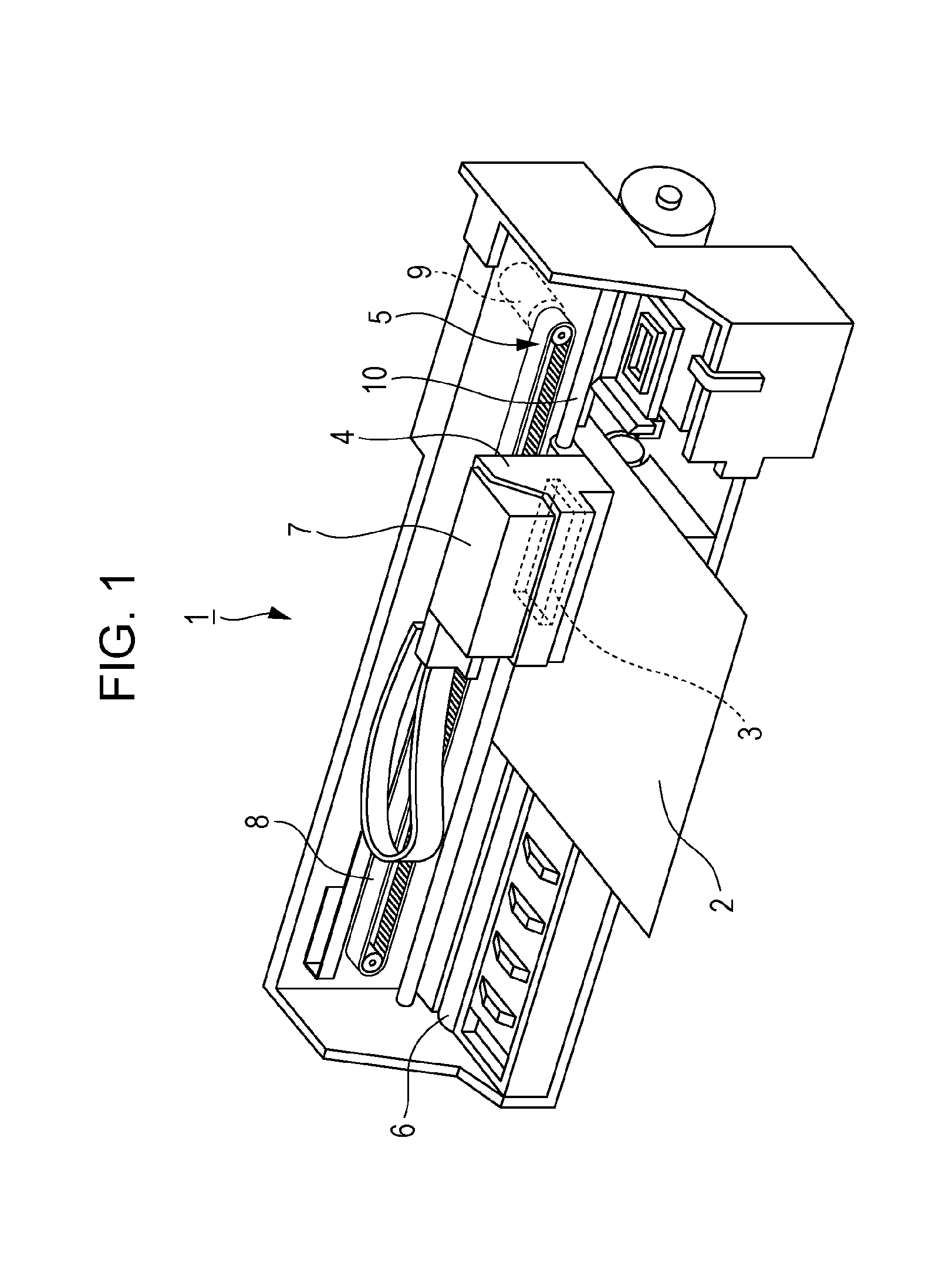
[0031]Hereinafter, the embodiments of the present invention will be described with reference to the attached drawings. In the embodiments described below, various limitations have been made as preferred embodiments of the invention, however, it is to be understood that the scope of the invention is not limited to the embodiments unless otherwise described to limit the invention in the following description. In the description below, an example ink jet printer (hereinafter, referred to as a printer) that is a kind of liquid ejecting apparatuses including an ink jet recording head (hereinafter, referred to as a recording head) that is a kind of liquid ejection head including a piezoelectric device according to an embodiment of the invention will be described.

[0032]With reference to FIG. 1, a structure of a printer 1 is described. The printer 1 is a device that records, for example, an image onto a surface of a recording medium 2 (a kind of target on which ink droplets are to be ejecte...


PUM


Abstract

A piezoelectric device includes a first substrate having an empty chamber, a diaphragm defining a surface of the empty chamber, a piezoelectric element formed by stacking a first electrode layer, a piezoelectric layer, and a second electrode layer in sequence from the diaphragm side, the piezoelectric element provided on the side of the diaphragm opposite to the empty chamber, and a second substrate provided on the side of the first substrate opposite to the diaphragm. The thickness of at least a part of the first substrate in an opening peripheral area of the empty chamber is thicker than the thickness in an area outside the opening peripheral area.

Description

BACKGROUND[0001]1. Technical Field[0002]The present invention relates to a piezoelectric device, a liquid ejection head, and a method of manufacturing the piezoelectric device, the piezoelectric device including a first substrate having an empty chamber and a piezoelectric element formed on a diaphragm that defines the empty chamber.[0003]2. Related Art[0004]Piezoelectric devices including piezoelectric elements have various applications, for example, liquid ejecting apparatuses and vibration sensors. For example, a liquid ejecting apparatus ejects (discharges) various kinds of liquids from a liquid ejection head by using the piezoelectric device. Examples of liquid ejecting apparatuses include image recording apparatuses such as ink jet printers and ink jet plotters. In recent years, liquid ejecting apparatuses that have the capability of accurately discharging a very small amount of liquid at predetermined positions have been provided in various manufacturing apparatuses. These ap...

Claims


Application Information

Patent Timeline
IPC IPC(8): B41J2/16H01L41/09B41J2/14H01L41/08
CPCB41J2/161H01L41/0805B41J2002/14266B41J2/14233B41J2/1623H01L41/0973B41J2/1632B41J2002/14241H10N30/2047H10N30/704
Inventor TAKABE, MOTOKI
Owner SEIKO EPSON CORP
Learn More