Blade and rotary machine having the same

Active Publication Date: 2020-08-27
MITSUBISHI HEAVY IND LTD
View PDF0 Cites 1 Cited by
  • Summary
  • Abstract
  • Description
  • Claims
  • Application Information

AI Technical Summary

Benefits of technology

The patent aims to provide a blade and a rotary machine that can effectively suppress separation of the flow from the blade surface. The objective is to improve the performance of the rotary machine by reducing the influence of flow separation on its operation.

Problems solved by technology

When separation of a flow occurs, work on the blade surface decreases, which may lead to deterioration of the performance or operation efficiency of the machine.

Method used


Image

  • Blade and rotary machine having the same
  • Blade and rotary machine having the same
  • Blade and rotary machine having the same

Examples


Embodiment Construction

[0059]Embodiments of the present invention will now be described in detail with reference to the accompanying drawings. It is intended, however, that unless particularly identified, dimensions, materials, shapes, relative positions and the like of components described in the embodiments shall be interpreted as illustrative only and not intended to limit the scope of the present invention.

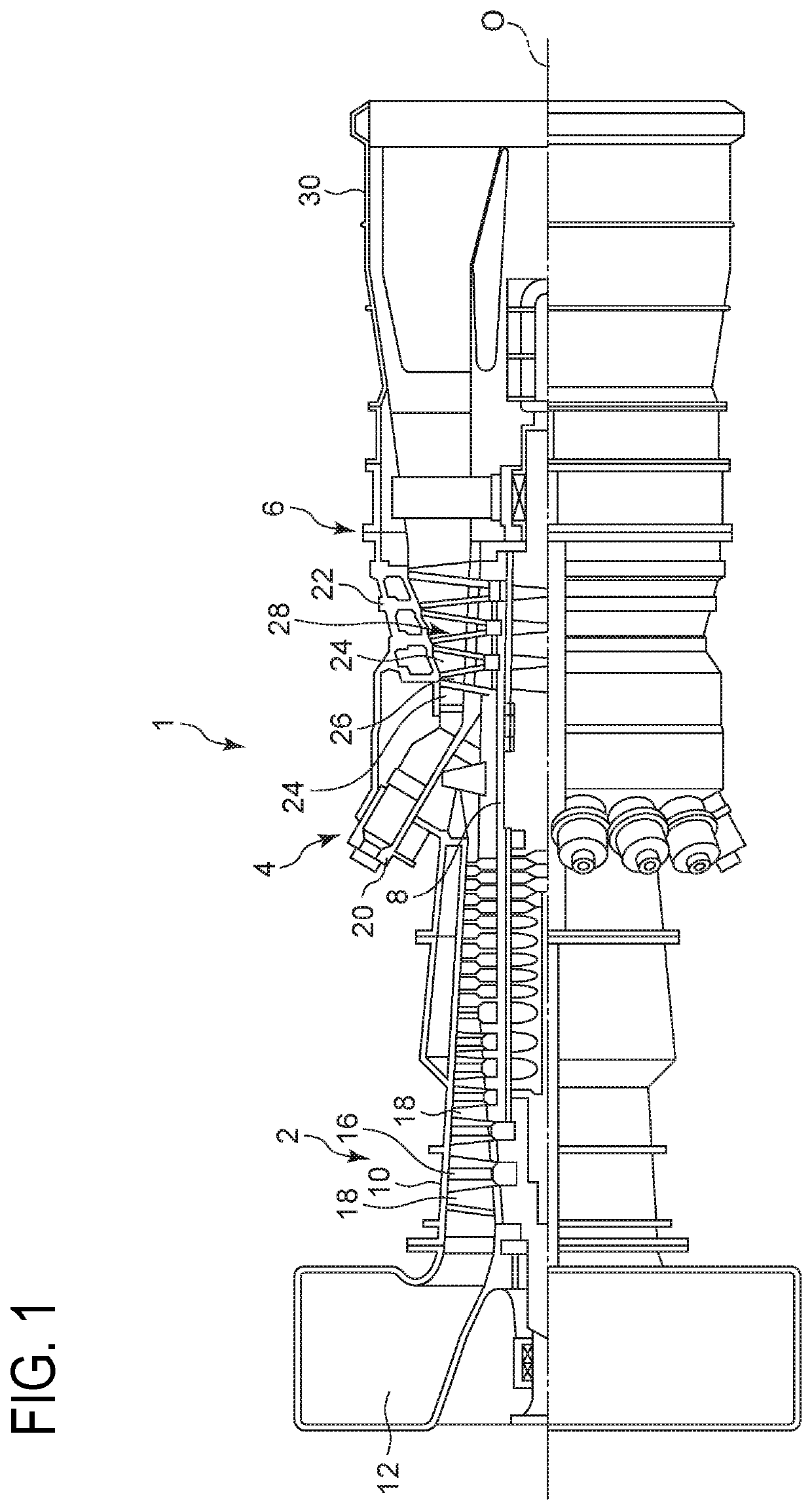
[0060]A rotary machine to which a blade according to the embodiment of the present invention is to be applied may be a compressor or a turbine, for instance, or a gas turbine that includes a compressor or a turbine. Firstly, with reference to FIG. 1, the gas turbine to which a blade according to some embodiments is to be applied will be described.

[0061]FIG. 1 is a schematic configuration diagram of a gas turbine according to an embodiment. As depicted in FIG. 1, the gas turbine 1 includes a compressor 2 for producing compressed air, a combustor 4 for producing combustion gas from the compressed air ...


PUM


Abstract

A blade includes: an airfoil portion having a pressure surface and a suction surface each of which extends between a base end and a tip end along a blade height direction between a leading edge and a trailing edge; and an internal passage passing through an inside of the airfoil portion, the internal passage having a first opening end opening to one of the pressure surface or the suction surface and a second opening end which is positioned closer to the tip end than the first opening end in the blade height direction and opening to a surface of the airfoil portion. When L is a length from the base end to the tip end in the blade height direction, a distance from the base end to the first opening end in the blade height direction is not less than zero and not greater than 0.3 L.

Description

TECHNICAL FIELD[0001]The present disclosure relates to a blade and a rotary machine having the same.BACKGROUND ART[0002]With regard to a blade to be applied to a machine such as a rotary machine, separation of a flow may occur in the vicinity of the blade surface of the blade, depending on the operation conditions or the like. When separation of a flow occurs, work on the blade surface decreases, which may lead to deterioration of the performance or operation efficiency of the machine. Thus, it is necessary to design the airfoil so as to reduce the loss generated by separation of the flow or the like.[0003]For instance, Patent Document 1 discloses a blade used for a turbine engine. A flow passage (channel) is disposed inside the airfoil portion of the blade. A gas extraction inlet disposed on the suction surface and the tip end of the airfoil portion is in communication via the flow passage. Furthermore, as a part of the air flow that flows along the airfoil portion is sucked into t...

Claims


Application Information

Patent Timeline
IPC IPC(8): F01D5/14F04D29/32
CPCF05D2240/307F01D5/145F05D2240/303F05D2250/70F04D29/544F05D2240/121F04D29/324F05D2240/301F05D2240/304F05D2250/12F04D29/682F04D29/684
Inventor YAMASHITA, SATOSHI
Owner MITSUBISHI HEAVY IND LTD
Why Eureka
Try Eureka