Thrust roller bearing

Active Publication Date: 2019-11-14
JTEKT CORP
View PDF7 Cites 0 Cited by
  • Summary
  • Abstract
  • Description
  • Claims
  • Application Information

AI Technical Summary

Benefits of technology

The technical effect of this patent is to prevent a crack from forming at the end of a hook that attaches a washer to a cage in a thrust roller bearing. This helps prevent the washer and cage from separating during use.

Problems solved by technology

However, in a process of forming the hook portion (the staking tab), there are cases in which tensile stress generated on a distal end portion of the hook portion produces a crack at a distal end of the hook portion.
However, this makes the distal end of the hook portion prone to cracking.
A crack produced in the hook portion not only leads to an appearance defect but also may cause a fragment to come off during processes such as heat treatment process.

Method used


Image

  • Thrust roller bearing
  • Thrust roller bearing
  • Thrust roller bearing

Examples


Embodiment Construction

[0021]Embodiments of the invention are described below with reference to FIGS. 1A to 6B. The embodiments described below are given as preferred specific examples for carrying out the invention and may specifically illustrate various preferable technical matters. It should be understood that the scope of the invention is not limited to the specific embodiments.

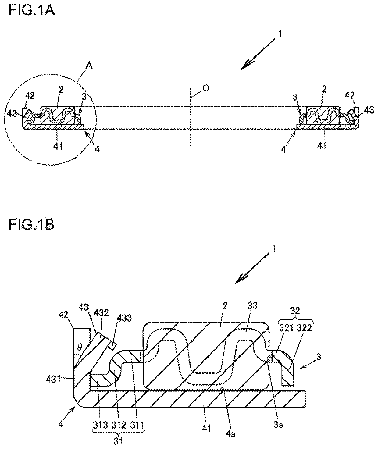
[0022]FIG. 1A is a sectional view illustrating a thrust roller bearing 1 according to an embodiment of the invention. FIG. 1B is an enlarged view of a portion A of FIG. 1A.

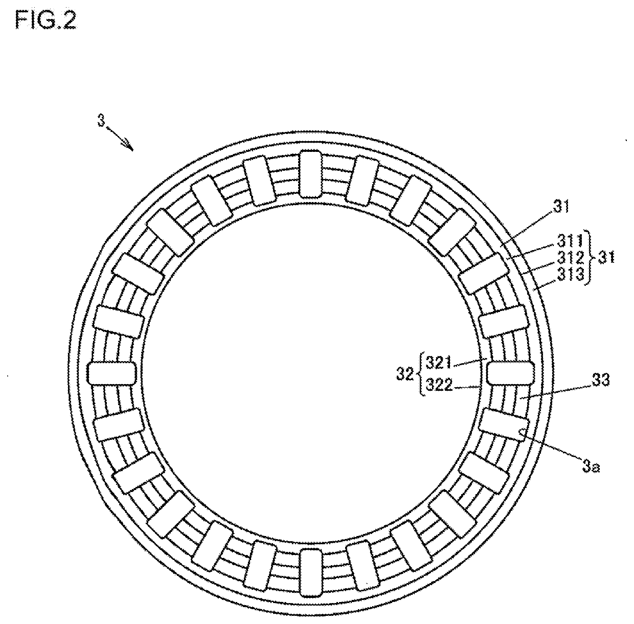
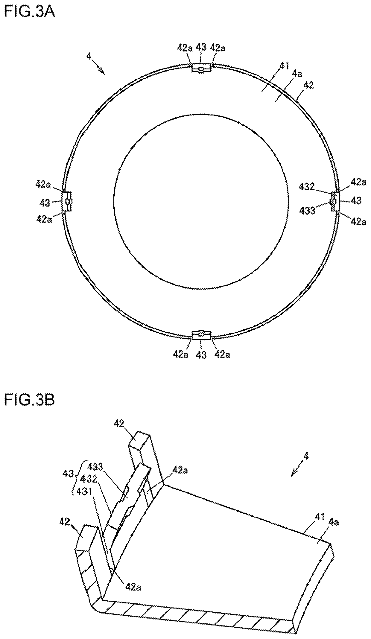
[0023]As illustrated in FIG. 1A and FIG. 1B, the thrust roller bearing 1 includes a plurality of cylindrical rollers 2, an annular cage 3, and a housing washer 4. The cylindrical rollers 2 are radially disposed. The cage 3 holds the plurality of rollers 2 in a manner that allows the rollers 2 to roll. The housing washer 4 is an annular washer, on which a raceway surface 4a, on which the plurality of rollers 2 roll, is formed and disposed on a first side with ...


PUM


Abstract

A thrust roller bearing includes rollers, a cage that holds the rollers in a manner that allows the rollers to roll, and a washer including a raceway surface on which the rollers roll. The washer includes a raceway portion that has the raceway surface and is disposed on a first axial side of the cage, and hook portions that extend toward a second axial side. Each of the hook portions includes a first projecting portion that extends toward the second axial side from the raceway portion, a second projecting portion that extends radially toward the rollers and toward the second axial side from an end portion of the first projecting portion on the second axial side, and a third projecting portion that further projects radially toward the rollers from an end portion of the second projecting portion on a side opposite to the first projecting portion.

Description

INCORPORATION BY REFERENCE[0001]The disclosure of Japanese Patent Application No. 2018-093201 filed on May 14, 2018 including the specification, drawings and abstract, is incorporated herein by reference in its entirety.BACKGROUND OF THE INVENTION1. Field of the Invention[0002]The invention relates to a thrust roller bearing, in which a plurality of rollers are radially held by a cage.2. Description of Related Art[0003]A thrust roller bearing is interposed between a non-rotary member and a rotary member in, for example, a vehicle transmission, to smooth rotation of the rotary member while receiving a thrust in an axial direction of a bearing axis. A thrust roller bearing includes a plurality of radially-disposed rollers, an annular cage, and an annular washer. The cage has a plurality of cage pockets that hold a plurality of rollers in a manner that allows the rollers to roll. The washer is disposed on a first axial side of the cage and includes a raceway surface, on which the plura...

Claims


Application Information

Patent Timeline
IPC IPC(8): F16C33/46F16C19/30
CPCF16C33/4605F16C19/305F16C19/32F16C33/583F16C33/546F16C33/588F16C33/586F16C2202/04F16C2220/42
Inventor YAMASHITA, KOTARONAKASHIMA, YOSHIHITO
Owner JTEKT CORP
Why Eureka
Try Eureka