Packing box for packing tube lamps
- Summary
- Abstract
- Description
- Claims
- Application Information
AI Technical Summary
Benefits of technology
Problems solved by technology
Method used
Image
Examples
first embodiment
The First Embodiment
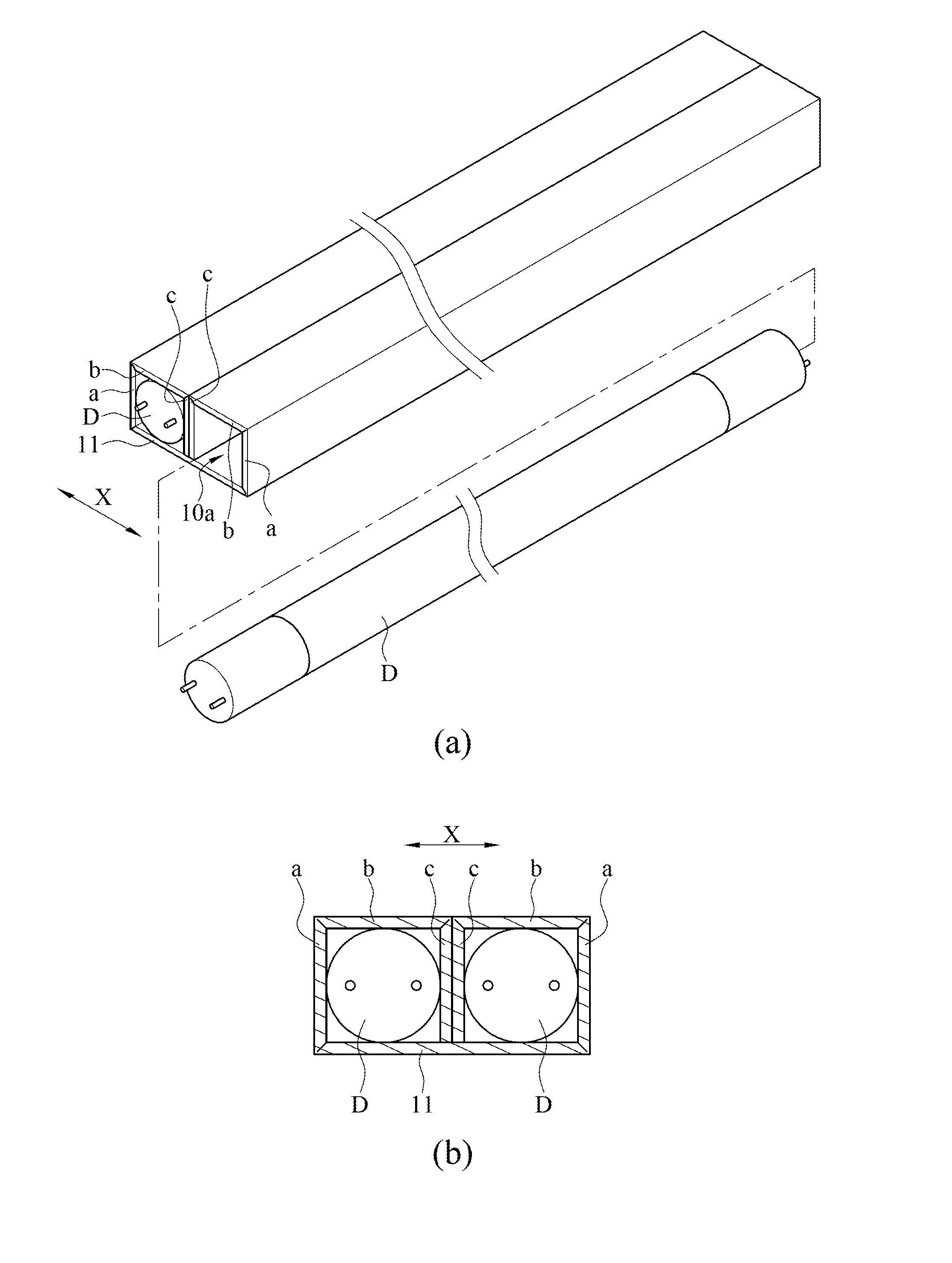
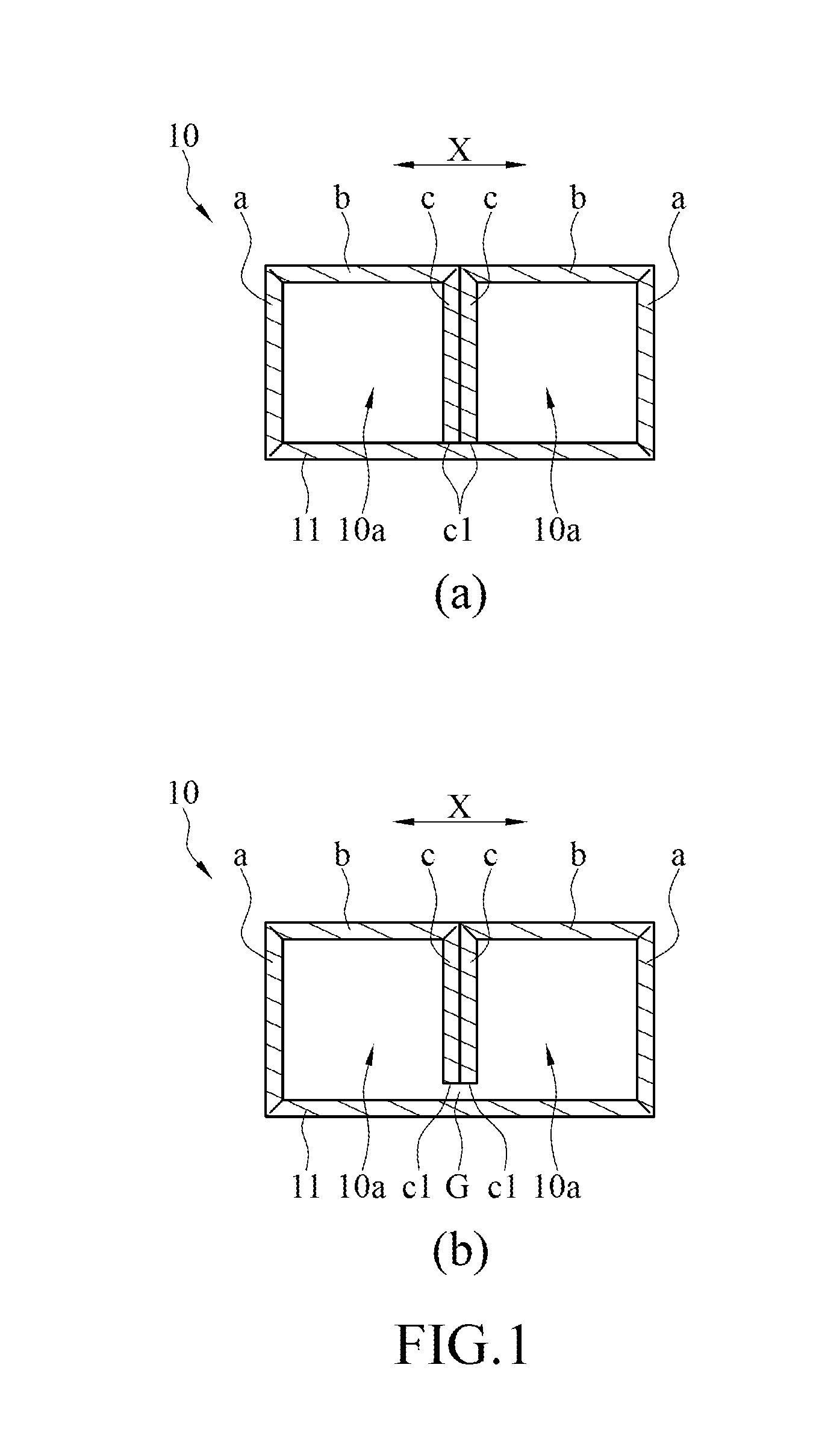
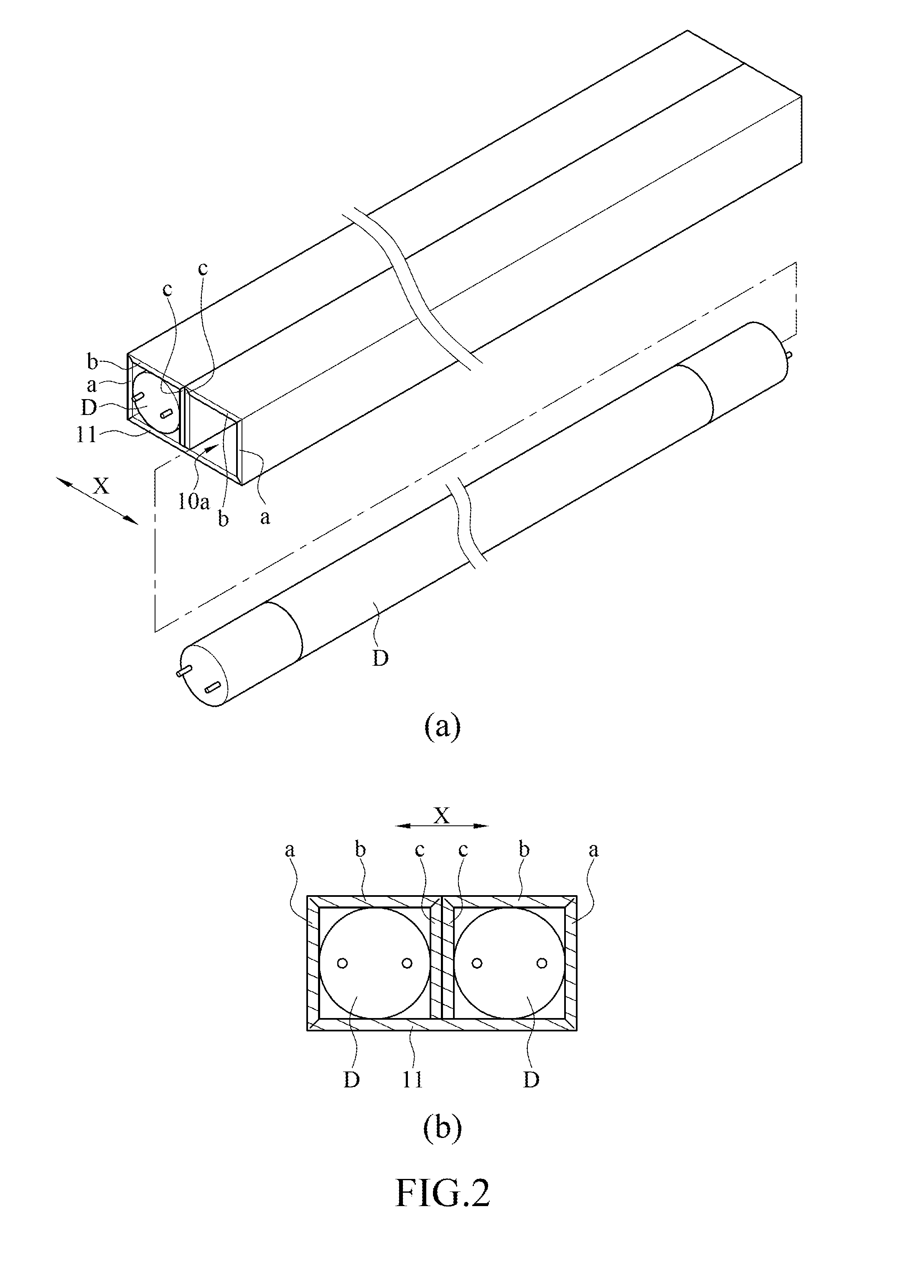
[0069]Referring to FIG. 1 and FIG. 2, according to a first embodiment of the instant disclosure, a packing box for packing tube lamps D is disclosed. FIG. 1(a) and FIG. 1(b) respectively illustrate two examples of middle cases 10 of the packing box. FIG. 1(a) and FIG. 1(b) are cross sections of the middle cases 10 in a width direction X. FIG. 2(a) illustrates a perspective view of the packing box of FIG. 1(a) and two tube lamps D packed in the middle case 10 of the packing box. FIG. 2(b) illustrates a cross section of the packing box in the width direction X. The packing box comprises a middle case 10. The middle case 10 can be utilized for wrapping at least two tube lamps D. The tube lamp D can be any lamp with tube shape, e.g., fluorescent lamps.
[0070]The middle case 10 is, but is not limited to, made by a piece of cardboard being designed to be bent to wrap the tube lamps D so as to protect the tube lamps D. The material of the middle case 10 is, but is not li...
second embodiment
The Second Embodiment
[0133]The instant disclosure provides a second embodiment. The difference between the first embodiment and the second embodiment is that the support section 11 of the first embodiment is not bent during the process of forming the receiving cavities 10a, but the support section 11 of the second embodiment is bent during the process of forming the receiving cavities 10a.
[0134]Referring to FIG. 25, the support section 11 comprises a bent edge 111 along the length direction of the tube lamp D. The support section 11 can be bent about the bent edge 111.
[0135]The support section 11 is bent about the bent edge 111 to (1) alter the alignment of the receiving cavities 10a or (2) form the receiving cavities 10a.
[0136](1) Regarding that the support section 11 is bent about the bent edge 111 to alter the alignment of the receiving cavities 10a, details are as follows.
[0137]Before the support section 11 is bent, the receiving cavities 10a have been formed already. The bend...
third embodiment
The Third Embodiment
[0156]The instant disclosure provides a third embodiment. The difference between the first embodiment and the third embodiment is that there are at least two layers of each of the side walls of the receiving cavity 10a of the third embodiment. More particularly, each of the receiving cavities 10a is formed by a plurality of side walls in the circumferential direction, and each of the side walls of the receiving cavity 10a has at least two layers in the radial direction (e.g., two or more side walls overlap one by one in the radial direction to form two or more layers). The inner layer of the side walls contacts the circumferential surface of the tube lamp D to have the tube lamp D tightly fit in the receiving cavity 10a.
[0157]In the embodiment, as shown in FIG. 32, the shape of the cross section of the receiving cavity 10a is a regular tetragon. Each of the receiving cavities 10a is formed by a plurality of double-layers side walls defined as a first layer 101 a...
PUM
 Abstract
Description
Claims
Application Information
 - R&D
- Intellectual Property
- Life Sciences
- Materials
- Tech Scout
- Unparalleled Data Quality
- Higher Quality Content
- 60% Fewer Hallucinations
Browse by: Latest US Patents, China's latest patents, Technical Efficacy Thesaurus, Application Domain, Technology Topic, Popular Technical Reports.
© 2025 PatSnap. All rights reserved.Legal|Privacy policy|Modern Slavery Act Transparency Statement|Sitemap|About US| Contact US: help@patsnap.com


