Positioning Device for an Optical Triangulation Sensor

a technology of positioning device and triangulation sensor, which is applied in the direction of surveying and navigation, using reradiation, engine control, etc., can solve the problem of limiting the speed at which measurements can be taken, and achieve the effect of quick and efficien

Active Publication Date: 2017-01-05
THIRD DIMENSION SOFTWARE
View PDF2 Cites 12 Cited by
  • Summary
  • Abstract
  • Description
  • Claims
  • Application Information

AI Technical Summary

Benefits of technology

[0010]At its most general, the present invention provides a tool or attachment jig for mounting an optical triangulation sensor on a turbine blade in a position to measure the gap between the distal tip of the turbine blade and the inner surface of the annular outer casing (also known as a shroud) in which the blade is rotatably located. Advantageously, the tool includes a device (e.g. a suitably configured accelerometer or gyroscope) for indicating the orientation of the sensor with respe...

Problems solved by technology

This limits the speed at wh...

Method used


Image

  • Positioning Device for an Optical Triangulation Sensor
  • Positioning Device for an Optical Triangulation Sensor
  • Positioning Device for an Optical Triangulation Sensor

Examples


Embodiment Construction

; FURTHER OPTIONS AND PREFERENCES

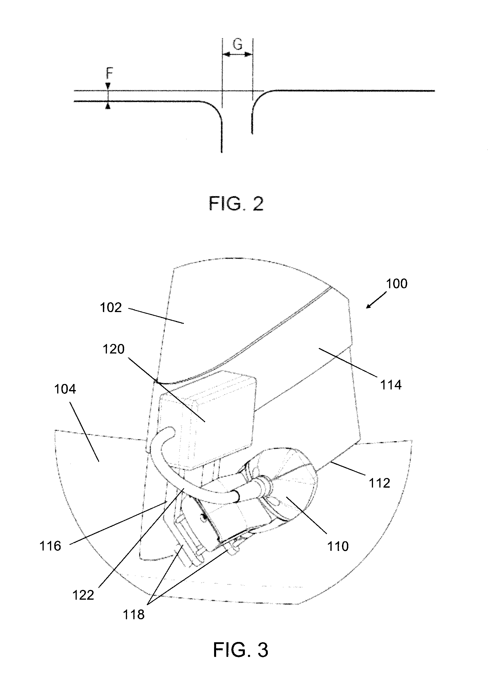
[0031]FIG. 3 is a perspective view of a positioning device 100 that is an embodiment of the invention. The positioning device 100 is mounted on a turbine blade 102, which is arranged to rotate within an annular casing, part of the inner surface 104 of which is shown in FIG. 3. A full front view of the arrangement is shown in FIG. 4, where a plurality of turbine blades 102 are mounted on and rotate with a central shaft 106 relative to the annular casing 108.

[0032]The positioning device 100 is mounted towards the distal end of the turbine blade 102, i.e. towards the end closer to the annular casing. As shown in FIG. 3, the purpose of the positioning device is to hold an optical triangulation sensor 110 in manner that permits it to measure the gap between the distal edge 112 of the turbine blade 102 and the inner surface 104 of the annular casing. The gap is an engineered radial spacing that permits rotation of the turbine blade without catching on the ...


PUM


Abstract

A tool or attachment jig for mounting an optical triangulation sensor on a turbine blade in a position to measure the gap between the distal tip of the turbine blade and the adjacent shroud. The tool includes a device for indicating the orientation of the sensor. This means that the tool can match a measurement from the optical triangulation sensor with a position on the circumference of the shroud. By taking a plurality of measurements as the turbine blade is rotated with respect to the annular casing, an angular profile for the gap between the turbine blade and the casing can be obtained in a much quicker and more efficient way than a conventional system.

Description

FIELD OF THE INVENTION[0001]The invention relates to measurement apparatus which uses triangulation principles to measure the physical geometry of articles and / or their relative position to each other. For example, the invention may be used with a laser triangulation sensor. In particular, the present invention concerns positioning the planar light beam of an optical triangulation sensor with respect to an object to track the object's separation from a reference surface as the object moves relative to the reference surface.BACKGROUND TO THE INVENTION[0002]Optical measurement systems which use a laser triangulation sensor to obtain dimensional information about objects are known. For example, such systems may be arranged to determine the distance of objects from the sensor or the profile of objects within the field of view of the sensor.[0003]Referring to FIG. 1, a conventional laser triangulation measurement device 1 comprises a light source 2 e.g. laser which is arranged to project...

Claims


Application Information

Patent Timeline
IPC IPC(8): G01S17/48F01D21/00
CPCF01D21/003G01B11/26G01B11/306G01B11/14F05D2270/804G01S17/48
Inventor MONKS, TIM
Owner THIRD DIMENSION SOFTWARE
Why Eureka
Try Eureka