
Islanding a plurality of grid tied power converters

a technology of power converters and grid tie-ins, which is applied in the direction of dc-ac conversion without reversal, climate sustainability, energy industry, etc., can solve the problems of unable to seamlessly transition multiple units between grid-tied and stand-alone mode, the extra generation is lost, and the renewable energy generation may exceed the load demand of the microgrid. achieve the effect of curtailing power generation

Active Publication Date: 2017-01-05
DYNAPOWER COMPANY
View PDF5 Cites 41 Cited by
  • Summary
  • Abstract
  • Description
  • Claims
  • Application Information

AI Technical Summary

Benefits of technology

The present patent is about using renewable energy sources and energy storage units to create self-sustaining microgrids for critical loads or remote areas. The patent describes a system where multiple power converters are combined to provide a combined power converter output to the load. The power converters are coupled together and synchronized to the external grid, allowing them to transition from grid-tied mode to microgrid mode and share the load. The control system includes a master controller that coordinates the slave controllers and makes the necessary adjustments to ensure the system operates efficiently. The technical effect of this patent is the creation of a flexible and reliable power system that can withstand abnormal external grid conditions and provide uninterrupted power to critical loads.

Problems solved by technology

Renewable energy sources such as photovoltaic / solar panels and wind turbines are intermittent sources subject to unpredictable and inconvenient weather patterns.
For example, renewable energy generation may exceed load demand of the microgrid.
Without energy storage capability, the extra generation is lost.
Unfortunately, existing implementation do not enable multiple units to be seamlessly transitioned between grid-tied and stand-alone mode.

Method used


Image

  • Islanding a plurality of grid tied power converters
  • Islanding a plurality of grid tied power converters
  • Islanding a plurality of grid tied power converters

Examples


Embodiment Construction

)

[0050]Other advantages of the present invention will be readily appreciated, as the same becomes better understood by reference to the following detailed description when considered in connection with the accompanying drawings, wherein:

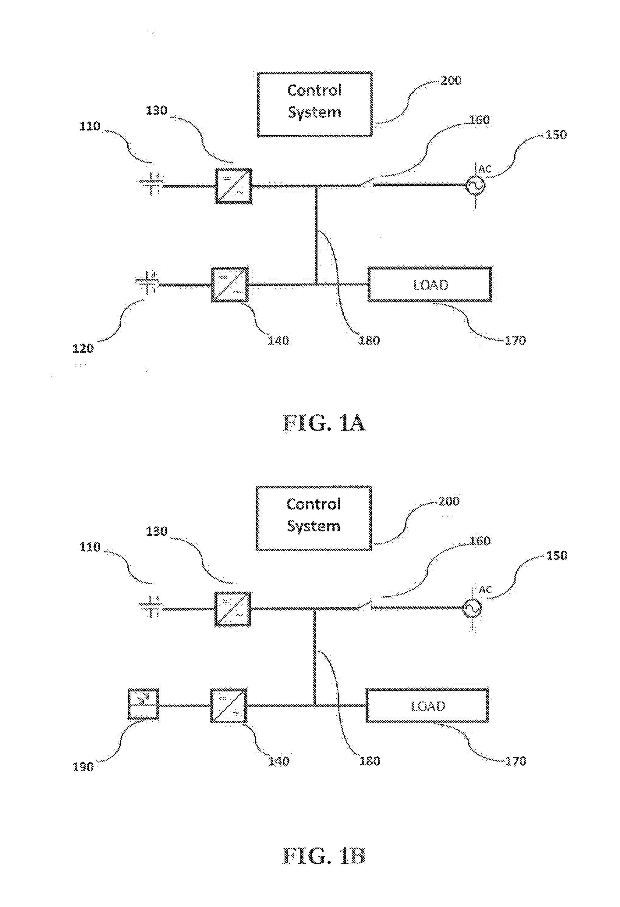
[0051]FIGS. 1A and 1B are exemplary embodiments of a system for islanding multiple grid-tied energy storage inverters to form a microgrid;

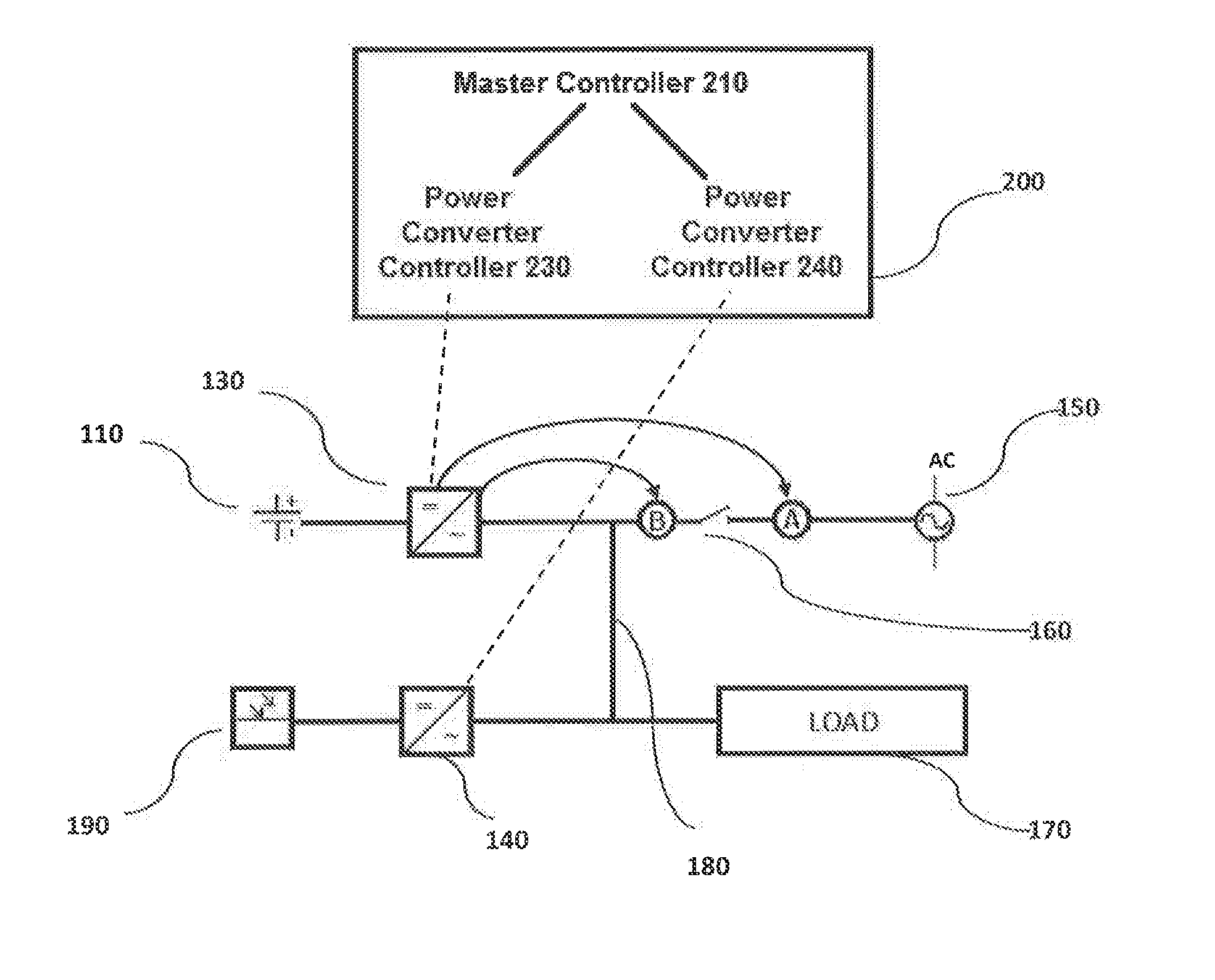
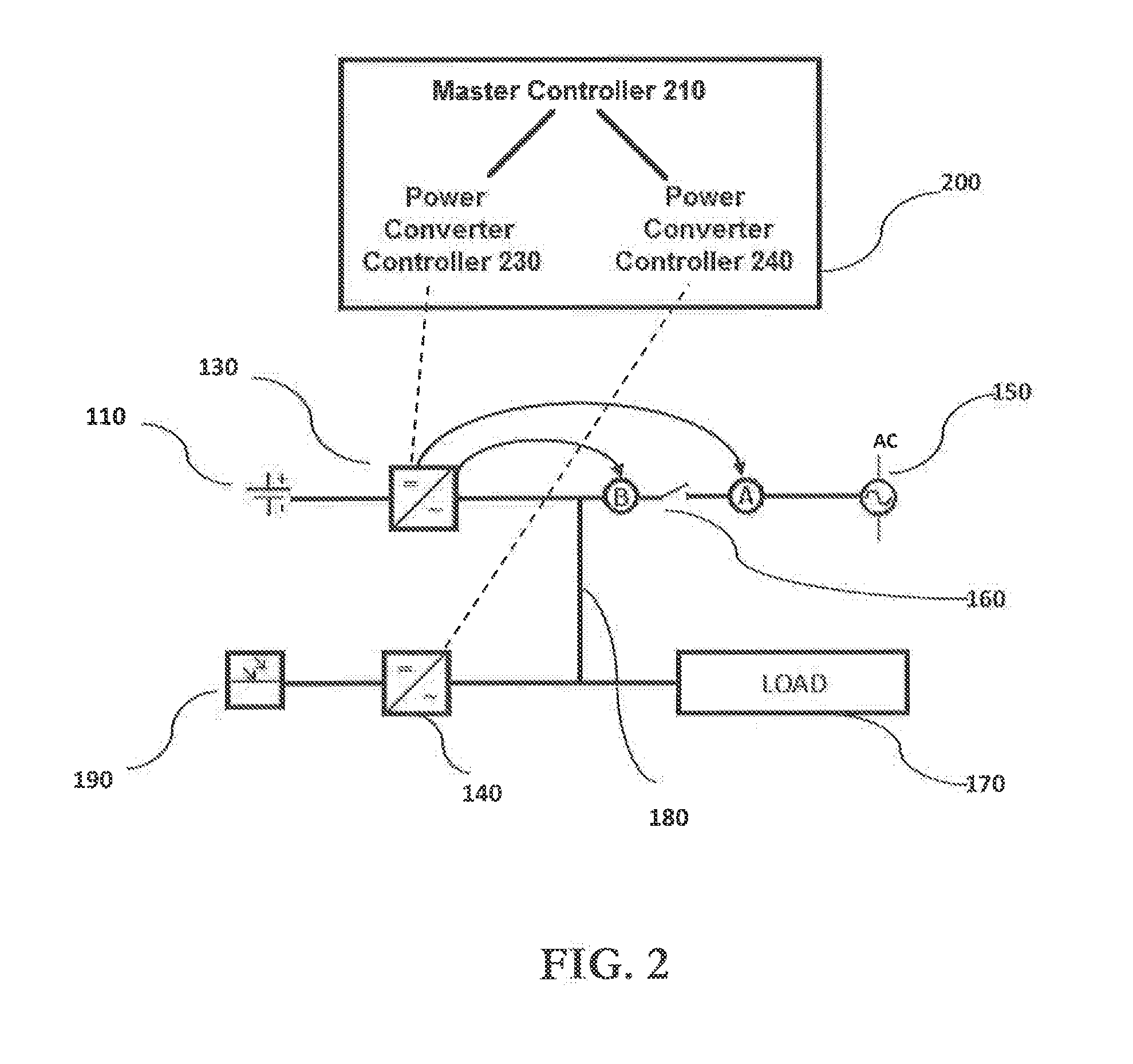
[0052]FIG. 2 illustrates an exemplary embodiment for controlling the transition and synchronization of power converters between the grid-tied and microgrid modes;

[0053]FIG. 3 illustrates a method in which a droop method is implemented to synchronize a plurality of power converters;

[0054]FIG. 4 illustrates a method in which a master / slave configuration is implemented to synchronize a plurality of power converters; and

[0055]FIG. 5 illustrates a method of controlling the power system according to an embodiment of the present invention in which the power system transitions from microgrid mode to grid-tied mode.

DETAILED...


PUM


Abstract

A power system having a plurality of power converters coupled together at a point of common coupling (PCC). The power converters are coupled to a load and provide a combined power converter output to the load. A switch is coupled in series between the PCC and an external grid. When the switch is closed, the power system is in a grid-tied configuration and when the switch is open, the power system is in a microgrid configuration. A control system coupled to the power converters enables the switch to open and close in response to a signal received from one or more sensors monitoring the external grid, enables the power converters to operate in a current control mode when the switch is closed, and transitions the power converters from grid-tied mode to microgrid mode and synchronize the power converters such that the converters share the load.

Description

RELATED APPLICATIONS[0001]The present patent document claims the benefit of the filing date under 35 U.S.C. §119(e) of Provisional U.S. Patent Application Ser. No. 62 / 188,278, filed July 2, 2015, which is hereby incorporated by reference.[0002]DESCRIPTIONFIELD OF THE INVENTION[0003]The present invention relates generally to power converters; and more specifically, to systems and methods for islanding a plurality of grid-tied power converters to form a microgrid.BACKGROUND OF THE INVENTION[0004]A power system may include distributed power sources (e.g., distributed generators, battery banks, and / or renewable resources such as solar panels or wind turbines to provide power supply to a grid (e.g., a microgrid having local loads and / or a utility grid). The power system may include a power converter, such as a power inverter, for converting power between a power source and a grid. Such power conversion may include AC / DC, DC / DC, AC / AC and DC / AC.[0005]A microgrid system can include a varie...

Claims


Application Information

Patent Timeline
IPC IPC(8): H02J3/38
CPCH02J3/383H02M7/42H02J3/388Y02P80/14H02J3/381H02J2300/10Y04S10/12Y02P80/15
Inventor SOMANI, APURVAPALOMBINI, JOHN C.
Owner DYNAPOWER COMPANY
Learn More