Method of dressing a tool

a tool and dressing technology, applied in the direction of total factory control, programme control, electric programme control, etc., can solve the problems of large number of strokes, and inability to influence the shape of the profile only with limitations during the dressing process, so as to prevent the undercutting of the gearing, increase the control of the resulting modifications, and improve the effect of production advantages

Active Publication Date: 2017-01-12
LIEBHERR VERZAHNTECHNIK GMBH
View PDF3 Cites 13 Cited by
  • Summary
  • Abstract
  • Description
  • Claims
  • Application Information

AI Technical Summary

Benefits of technology

[0012]In a second variant, the specific modification of the surface geometry of the tool at at least two rolling angles and / or a pitch of the specific modification of the surface geometry of the tool can be specifiable and, in addition, an association of a specific radius of the dresser with a specific radius of the tool can take place. The association of a specific radius of the dresser with a specific radius of the tool has technical production advantages, on the one hand, for example in that an undercutting of the gearing is prevented. Alternatively or additionally, the association of the radii can, however, also be used for a direct positioning of a modification present in the dresser on the tool.
[0013]In a third variant, an association of two specific radii of the dresser with two specific radii of the tool can take place. Such an association of two radii of the dresser with two radii of the tool can, on the one hand, bring about technical production advantages. On the other hand, such an association allows an increased control of the resulting modifications and can for example when a modified dresser is used, position the modification at corresponding positions of the tool or can produce a compression or a stretching of the modification on the tool.

Problems solved by technology

In methods known from the prior art for dressing using a profile roller dresser, there is, however, the disadvantage that, with a given dresser, the profile shape can only be influenced with limitations during the dressing process.
The process hereby becomes very uneconomic.
However, a very large number of strokes are required due to the small contact surface and the profile has a high degree of roughness.
However, profile modifications can only be roughly approximated, whereby shape deviations arise.
However, in such methods in accordance with the state of the art, it was only possible to influence the profile angle, which is produced during dressing, via the dressing kinematics.
However, additional possibilities of influencing the modifications naturally result in single-flank dressing which are not present in two-flank dressing due to the existing dependencies between the modifications on the left flank and on the right flank.

Method used


Image

  • Method of dressing a tool
  • Method of dressing a tool
  • Method of dressing a tool

Examples


application examples

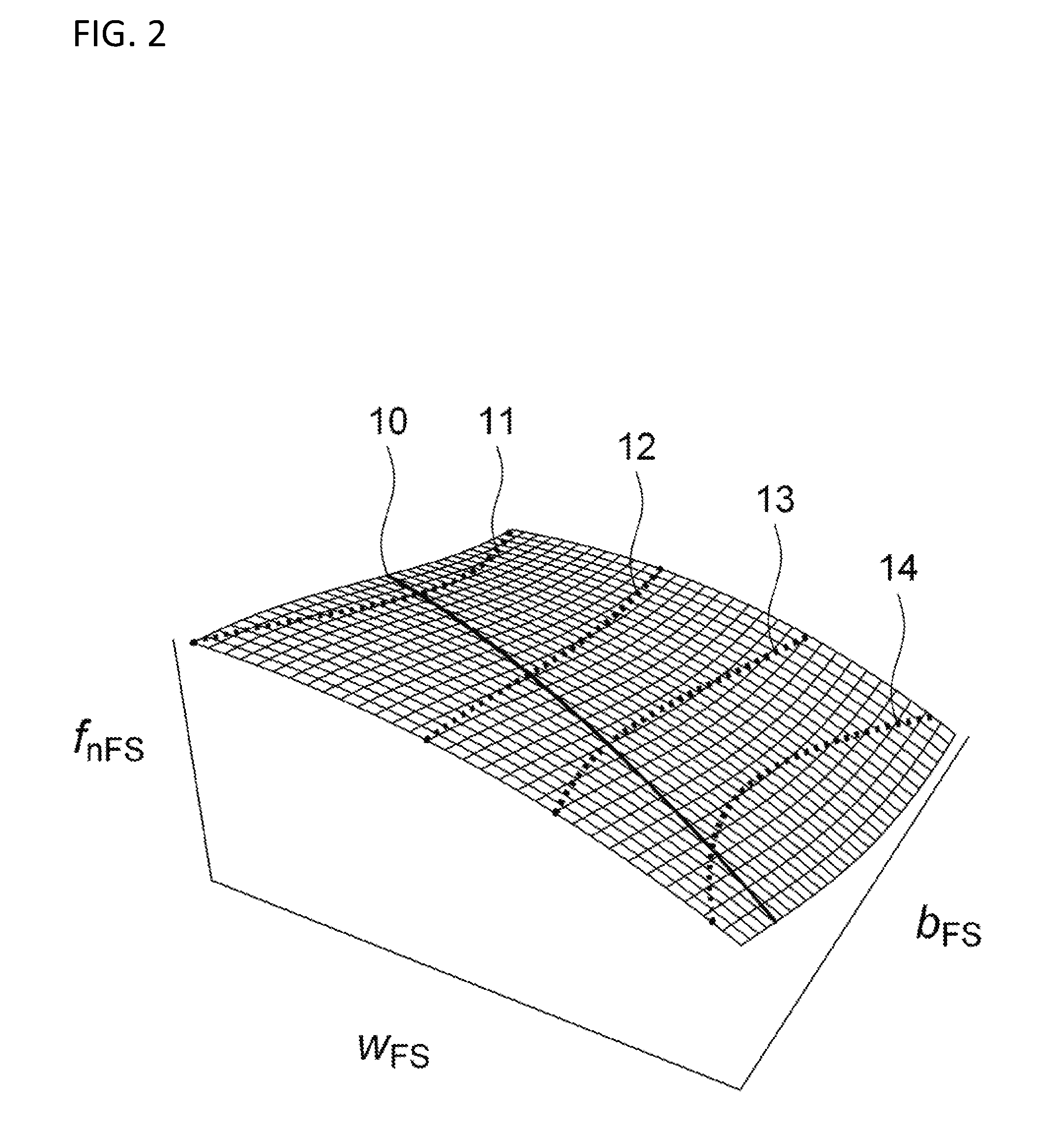
[0459]Some simple application examples will be described in the following for which in part the advantage of the present disclosure described here with respect to the prior art will be illustrated and which at the same time are intended to illustrate the method a little.

[0460]A particular subclass of modifications which can be produced using the method described here and which is already of great relevance today is represented by modifications which are given by a second degree polynomial in w and z. Such modifications ƒP2 can generally be described by

ƒP2(wF,zF)=Aw0z0+Aw1z0·wF+Aw0z1·zF+Aw1z1·wF·zF+Aw2z0·wF2+Aw0z2·zF2  (101)

where the coefficients A are real numbers freely selectable within certain limits. If ƒP2 is resolved in accordance with equation (100) in FFtC, FFtL and FKFt and if the approach

FFtC(XF)=KF02·XF2+KF01·XF+KF00

FFtL(XF)=KF11·XF+KF10

FKFt(XKF)=KKF2·XKF2+KKF1·XKF  (102)

with XKF=wF sin ρKF+zF cos ρKF is selected, a coefficient comparison produces 6 equations from which...


PUM

PropertyMeasurementUnit
surface geometryaaaaaaaaaa
specific radiusaaaaaaaaaa
surfaceaaaaaaaaaa

Abstract

A tool which can be used for gear manufacturing machining of a workpiece may be dressed on a dressing machine, and the dressing may take place with line contact between the dresser and the tool. A specific modification of the surface geometry of the tool is produced by the suitable selection of the position of the dresser with respect to the tool during dressing. The specific modification of the surface geometry of the workpiece is specifiable with regard to various parameters.

Description

CROSS REFERENCE TO RELATED APPLICATION[0001]This application claims priority to German Patent Application No. 10 2015 008 964.1, entitled “Method of Dressing a Tool,” filed Jul. 10, 2015, the entire contents of which is hereby incorporated by reference in its entirety for purposes.TECHNICAL FIELD[0002]The present disclosure relates to a method of dressing a tool, which can be used for the gear manufacturing machining of a workpiece, on a dresser, wherein the dressing takes place with line contact between the dresser and the tool. The present disclosure in particular relates to a method of dressing a grinding worm which can be used for the gear manufacturing machining of a workpiece and / or to a method of dressing a tool which can be used for a gear generating machining of a workpiece The tool can in particular be used for the generating grinding of a toothed workpiece, in particular for the generating grinding of a gear wheel.BACKGROUND AND SUMMARY[0003]Two processes are essentially ...

Claims


Application Information

Patent Timeline
Patent Type & Authority Applications(United States)
IPC IPC(8): B23F23/12G05B19/27B23F19/05B23F19/00B23F23/00
CPCB23F23/1225B23F19/002B23F23/003G05B2219/50117G05B19/27G05B2219/39573B23F19/052G05B19/40937G05B19/186Y02P90/02B24B53/075B24B53/085B24B53/06B23F5/02
Inventor WUERFEL, ROBERT
Owner LIEBHERR VERZAHNTECHNIK GMBH
Why Eureka
Try Eureka