Diamond blade

a diamond blade and diamond technology, applied in the field of diamond blades, can solve the problems of limited and not necessarily satisfactory prevention of wobbling, inability to perform tension adjustment of the core, and significant problems, and achieve the effect of preventing undercutting and small wobbling

Inactive Publication Date: 2006-09-05
ALLIED MATERIAL
View PDF6 Cites 9 Cited by
  • Summary
  • Abstract
  • Description
  • Claims
  • Application Information

AI Technical Summary

Benefits of technology

[0008]In consideration of the aforementioned circumstances, the present invention proposes a blade capable of preventing undercutting and further reinforcing a core with small wobbling.

Problems solved by technology

When the thickness of the core is reduced, dust resulting from cutting enter clearances between the core and cutting grooves to wear particularly portions around junctions between the core and the superabrasive layers (hereinafter referred to as undercutting), leading to a significant problem.
However, the aforementioned blade mounted with the core reinforcing diamond segments depends on the reinforcing diamond segments for preventing wobbling during cutting, and hence prevention of wobbling is limited and not necessarily satisfactory.
In other words, the core is reinforced due to the rigidity of the radially formed diamond segments and hence circumferential rigidity of the core tends to be insufficient although radial rigidity is improved, to possibly cause wobbling.
Further, the diamond segments are provided on the substantially intermediate positions between the outer periphery of the core and the center of the blade and hence there is an apprehension that tension adjustment of the core cannot be performed and the core cannot be completely inhibited from wobbling.
If dry cutting is performed with a blade not subjected to the aforementioned tension adjustment (tensioning), heat is generated around superabrasive layers to disadvantageously expand the core by thermal expansion and wobble the same.
While wobbling can be prevented despite slight expansion of the outer periphery if tension adjustment is performed in this case, the aforementioned blade causes this problem due to impossibility of tension adjustment.
Therefore, cutting must disadvantageously be frequently interrupted in order to cool the blade.
While the aforementioned blade aims at preventing wobbling with reinforcing superabrasive layers, wobbling is frequently caused due to thermal expansion of the core resulting from heat generation during use of the blade in practice, and hence tension adjustment must be previously performed.

Method used


Image

  • Diamond blade
  • Diamond blade
  • Diamond blade

Examples


first embodiment

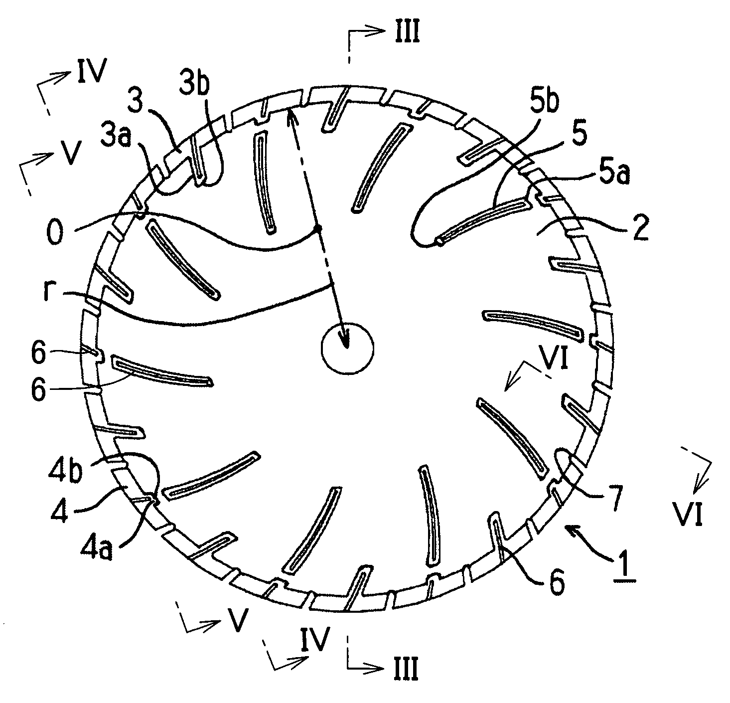
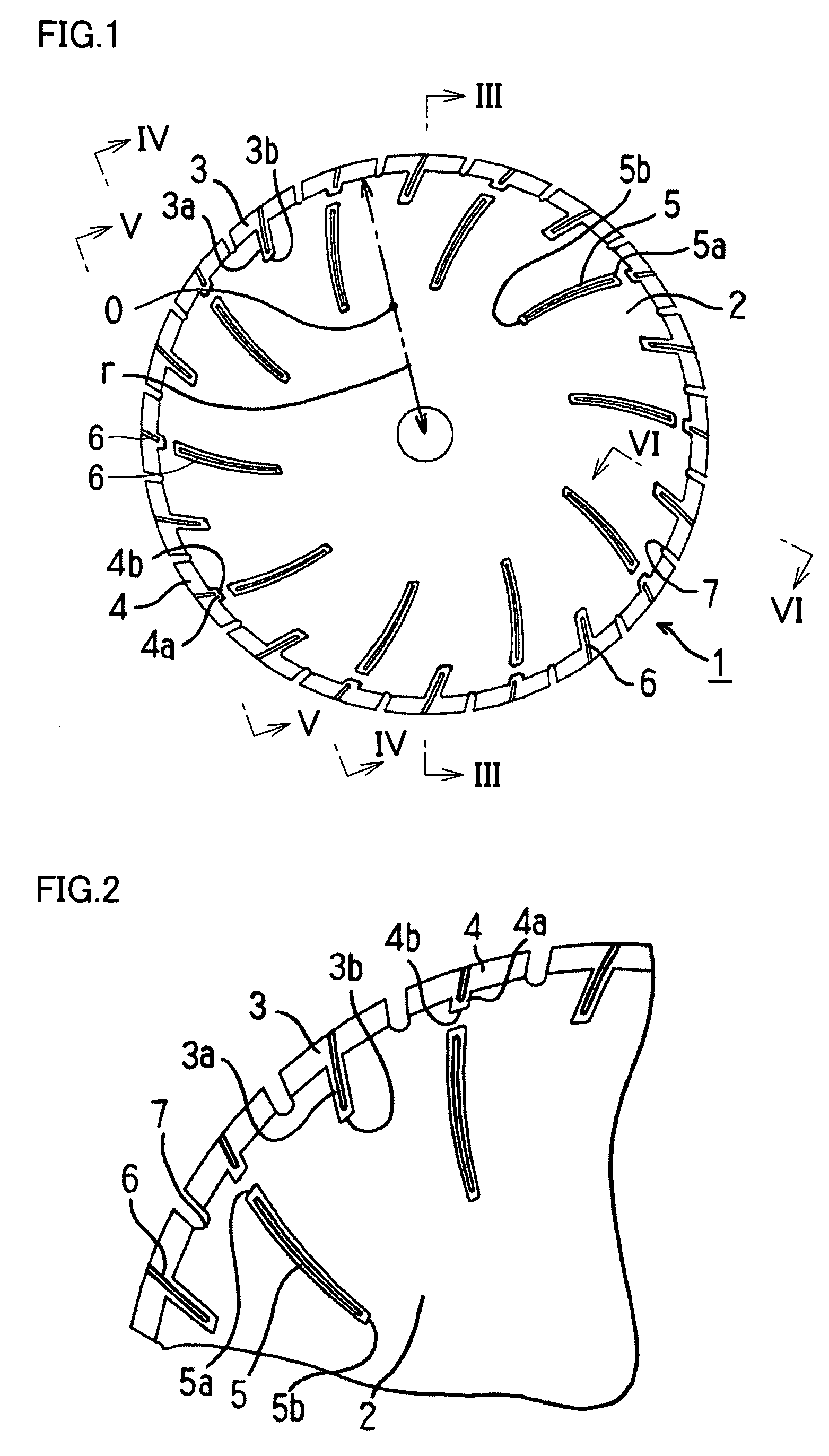
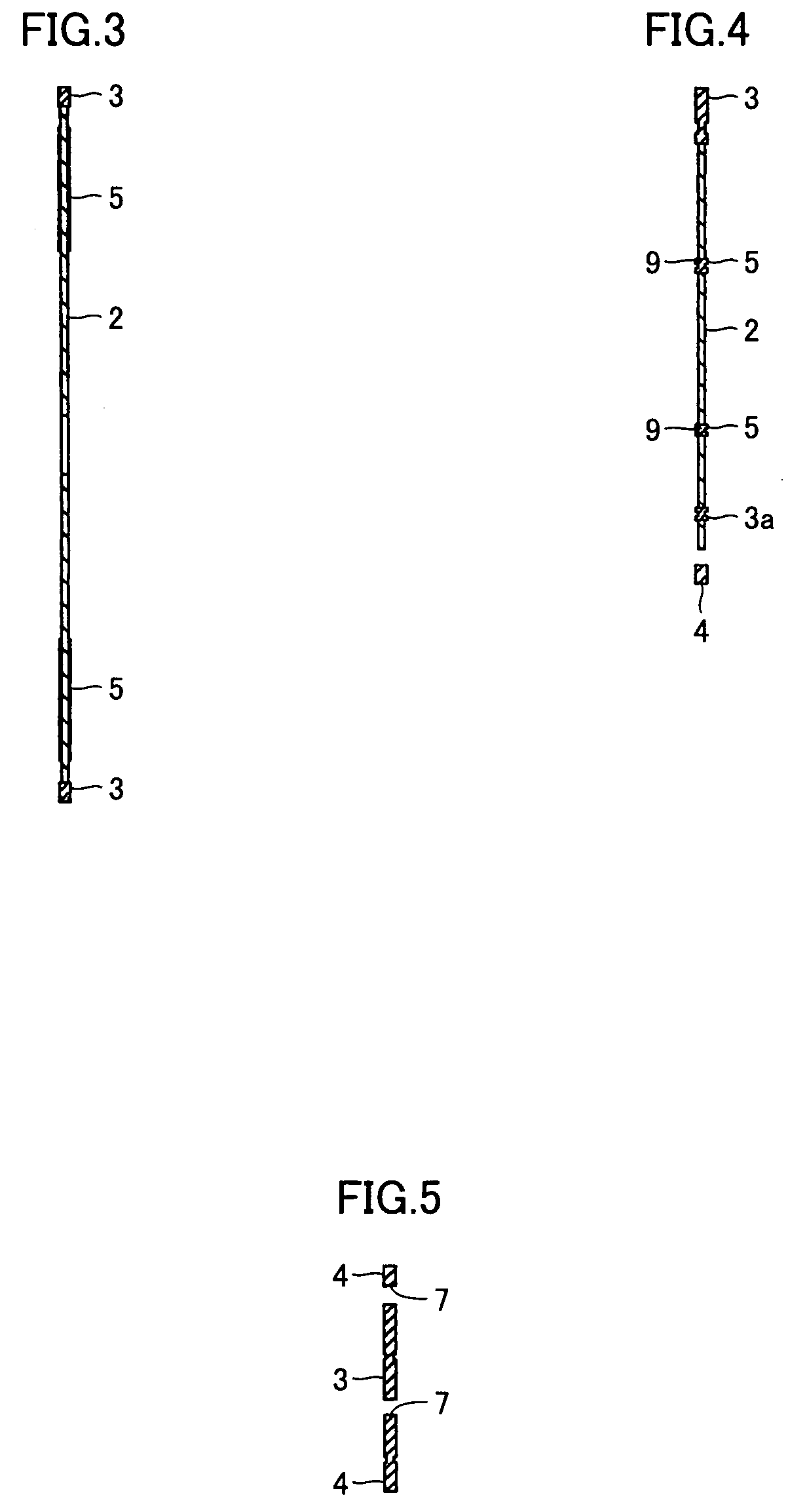
[0038]FIGS. 1 and 2 show a blade according to the present invention. Slots 7 are provided on the outer peripheral edge of a core 2, and first superabrasive layers 3 and second superabrasive layers 4 are alternately bonded to portions of the outer peripheral surface of the core located between the slots 7. The first superabrasive layers 3 are provided with extensions 3a partially extended toward the inner periphery of the core 2, while the second superabrasive layers 4 are provided with extensions 4a partially extended toward the inner periphery of the core 2. Further, reinforcing superabrasive layers 5 are provided on the inner peripheral sides of the extensions 4a of the second superabrasive layers 4. The extensions 4a of the second superabrasive layers 4 and the reinforcing superabrasive layers 5 are separate from each other. Portions of the core 2 are thus located between these superabrasive layers so that the core 2 itself is increased in strength to hardly wobble in cutting. In...

second embodiment

[0050]Referring to FIG. 9, a blade according to a second embodiment of the present invention is different from the blade according to the first embodiment in a point that no extensions are provided on second superabrasive layers 4. This blade also has effects similar to those of the blade according to the first embodiment.

third embodiment

[0051]Referring to FIG. 10, inner peripheral ends 4b of extensions 4a of second superabrasive layers 4 are located inward beyond a line connecting inner peripheral sides of adjacent slots 7 with each other in a diamond blade according to a third embodiment of the present invention. In other words, a relation expressed as h42 holds in FIG. 10. There is an apprehension that first superabrasive layers 3 and the second superabrasive layers 4 are subjected to resistance in cutting and tend to be bent in portions of the line connecting the inner peripheral sides of the slots 7 with each other, and this is prevented due to reinforcement with extensions 3a and the extensions 4a. While no provision of the extensions 4a on the inner peripheral sides of the second superabrasive layers 4 is also in the range of the present invention, the extensions 4a are preferably provided on the inner peripheral sides of the second superabrasive layers 4 in view of further reinforcement of the core 2 as desc...


PUM

PropertyMeasurementUnit
diameteraaaaaaaaaa
heightaaaaaaaaaa
compressive strengthaaaaaaaaaa

Abstract

In relation to a blade cutting stone or concrete, a blade, preventing wearing of a core while preventing the core from wobbling, cuttable at a stable speed is provided. In a blade formed by providing slots on the outer peripheral edge of a circular core and fixing a superabrasive layer to a portion of the outer peripheral surface of the core located between the slots, the superabrasive layer consists of a first superabrasive layer having an extension formed by partially extending the superabrasive layer toward the inner periphery of the core and a second superabrasive layer. A reinforcing superabrasive layer extending from the outer periphery toward the inner periphery of the core is formed on the inner peripheral side of the second superabrasive layer while the reinforcing superabrasive layer is located closer to the outer periphery than a radial central portion of the core, and an outer peripheral end of the reinforcing superabrasive layer is located closer to the outer periphery than an inner peripheral end of the extension of the first superabrasive layer. The second superabrasive layer can also be provided with an extension having a relatively short radial length with respect to the extension of the first superabrasive layer.

Description

TECHNICAL FIELD[0001]The present invention relates to a diamond blade, and more particularly, it relates to a blade for dry-cutting a hard and brittle material such as stone or concrete.BACKGROUND ART[0002]A diamond blade is used for cutting a hard and brittle material such as stone or concrete. A general example of this blade is a segmented blade shown in FIG. 12 formed by providing slots on the outer peripheral edge of a circular core while providing superabrasive layers on portions of the outer peripheral surface located between these slots, and the superabrasive layers are prepared by bonding superabrasive grains to each other through a metal bond or the like. The superabrasive layers are bonded to the core by brazing, welding or simultaneous sintering for bonding the superabrasive layers to the core simultaneously with sintering.[0003]The superabrasive layers of the blade have recently been reduced in thickness, and the thickness of the core must also be reduced following this....

Claims


Application Information

Patent Timeline
Patent Type & Authority Patents(United States)
IPC IPC(8): B28D1/04B23F21/03B23D61/02B24D5/12B28D1/12
CPCB23D61/025B28D1/121B24D5/12
Inventor KOIKE, AKIHIROHIRATA, TAKAHIRO
Owner ALLIED MATERIAL
Why Eureka
Try Eureka