Connection unit

a technology of connecting unit and housing portion, which is applied in the direction of cell components, electrical apparatus, batteries, etc., can solve the problems of limiting the deformation of the tolerance absorption portion, the limit of the distance between the two housing portions of the bus bar, and the deformation of the bar module, so as to reduce the number of components, facilitate the assembly of the plurality of bus bars, and improve assembly performance

Active Publication Date: 2017-01-12
TOYOTA JIDOSHA KK
View PDF7 Cites 6 Cited by
  • Summary
  • Abstract
  • Description
  • Claims
  • Application Information

AI Technical Summary

Benefits of technology

[0005]In view of this, an object of the present invention is to provide a connection unit which allows variations in overall length of a plurality of storage elements in a predetermined direction at the time when the plurality of storage elements aligned in the predetermined direction is electrically connected to each other, and which allows easy assembly thereof.
[0007]In the first aspect of the present invention, the plurality of bus bar units is individually provided as a unit along the rail member, so that each of the bus bar unit can move independently in a longitudinal direction of the member (a direction where respective electrode terminals of the storage elements adjacent to each other are aligned). Accordingly, it is possible to adjust a distance between the bus bar units adjacent to each other according to tolerance of the storage elements in the predetermined direction without depending on other bus bar units. As a result, entire assembly tolerance in the plurality of storage elements aligned in the predetermined direction can be absorbed (permitted) by adjusting respective distances between the bus bar units independent from each other, thereby making it possible to easily assemble the plurality of bus bars.
[0008]Further, the rail member can be configured to include a slit allowing the engagement portion to move along the predetermined direction; an engagement rail configured to engage with the engagement portion; an outlet portion provided at a position corresponding to an exhaust valve configured to exhaust gas generated in the storage element to its outside, the outlet portion extending in the predetermined direction so as to form a gas discharge path provided generally in parallel with the engagement rail; and a mounting portion extending along the outlet portion and configured such that a temperature sensor configured to detect a temperature of the storage elements is provided therein. At this time, the engagement rail, the outlet portion, and the mounting portion can be configured to, be formed integrally with each other so as to be aligned in a direction generally perpendicular to the predetermined direction. Since the gas outlet portion and the mounting portion for a temperature sensor are integrated with the rail member, it is possible to reduce the number of components. In addition, it is not necessary to provide respective components (spaces) individually, so that assembly performance is improved. Further, the temperature sensor is provided in the mounting portion extending along the outlet portion (the gas discharge path), thereby making it possible to accurately detect the temperature of the storage elements at the time of gas generation and to determine a mounting position of the temperature sensor to a given position along the predetermined direction. This improves a degree of freedom of the assembly of the temperature sensor.
[0009]Further, each of the bus bar units can further include a voltage detection line connected to the bus bar and configured to detect a voltage of the storage element. Further, the rail member can include a detection line placement portion extending along a direction where the plurality of bus bar units is aligned. The voltage detection line extending from the bus bar unit placed in the rail member via the engagement portion can be configured to be extended in the detection line placement portion generally in parallel with the predetermined direction. Accordingly, with respect to the plurality of bus bar units aligned along the rail member, the voltage detection lines extending from the bus bars are gathered in the detection line placement portion extending along the direction where the plurality of bus bar units is aligned. This makes it possible to achieve efficiency of a placement space for the voltage detection lines.
[0010]Further, the engagement portion can be made of thermo plastic resin, and at least part of the voltage detection line including a connection region with the bus bar can be configured to be covered with the thermo plastic resin. The bus bar unit can be configured such that the bus bar and the voltage detection line are formed integrally with each other. Since the bus bar and the voltage detection line are provided integrally with the bus bar unit, assembly tolerance of each component in the bus bar unit can be reduced. In addition, it is not necessary to attach the voltage detection line to the bus bar individually, thereby making it possible to improve assembly performance. Further, since at least part of the voltage detection line including the connection region with the bus bar is covered with the thermo plastic resin, it is possible to restrain corrosion of the voltage detection line including the connection region with the bus bar.

Problems solved by technology

However, the bus bar module of JP 2012-243608 A has a limit in the deformation of the tolerance absorption portion.
That is, there is a limit to widen the distance between the two bus bar accommodation portions.

Method used


Image

  • Connection unit
  • Connection unit
  • Connection unit

Examples


Embodiment Construction

[0020]The following describes an embodiment of the present invention.

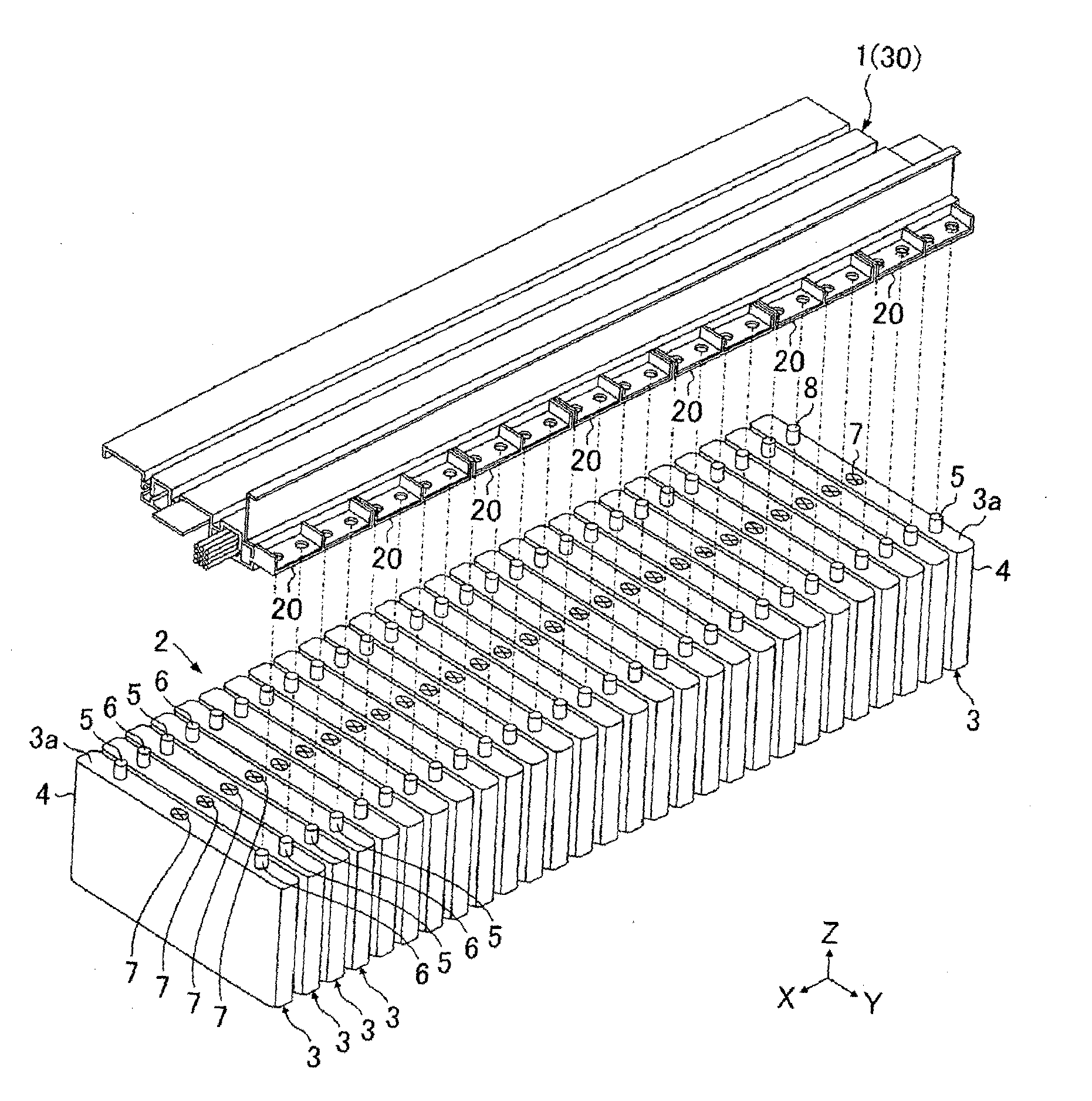
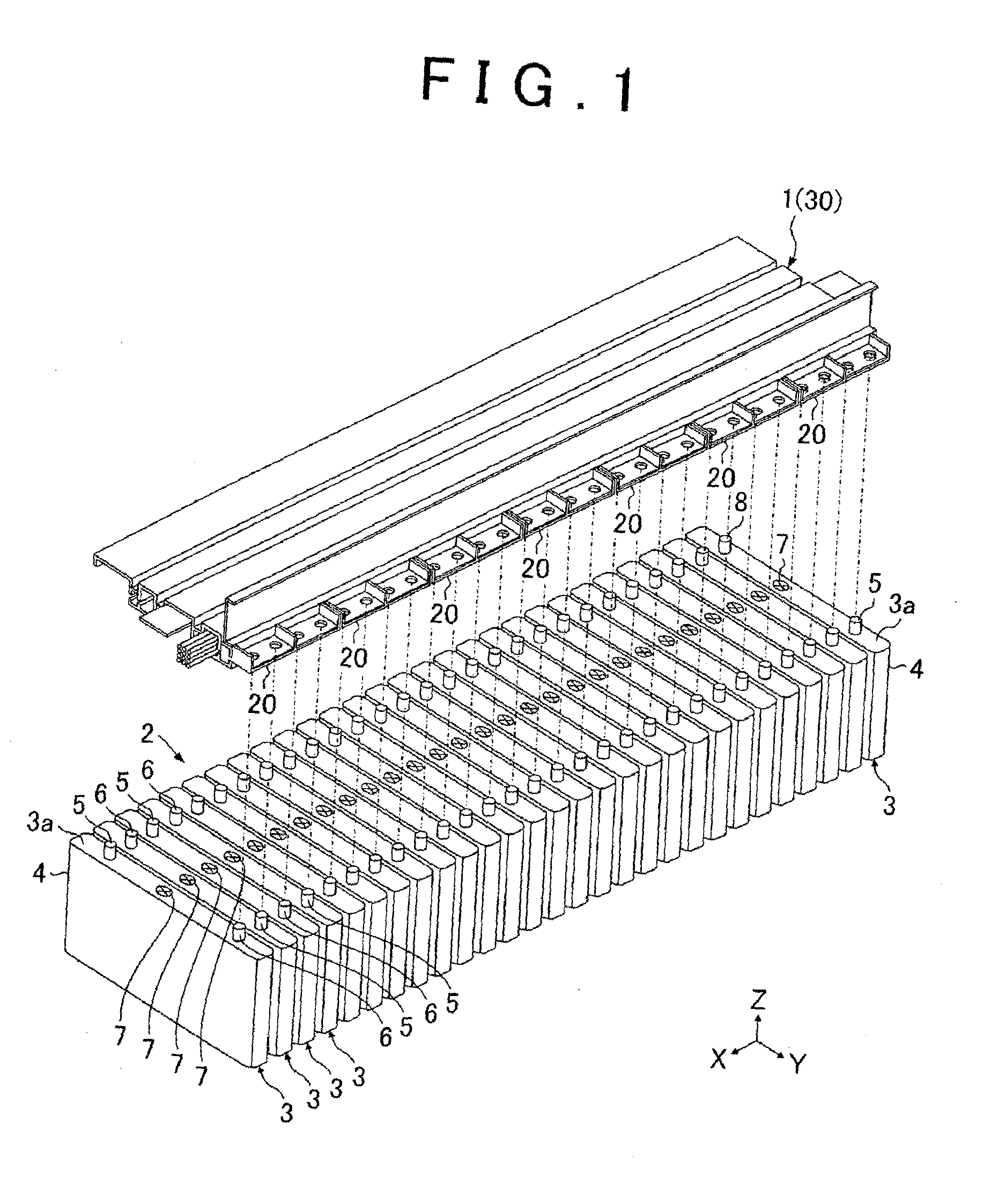
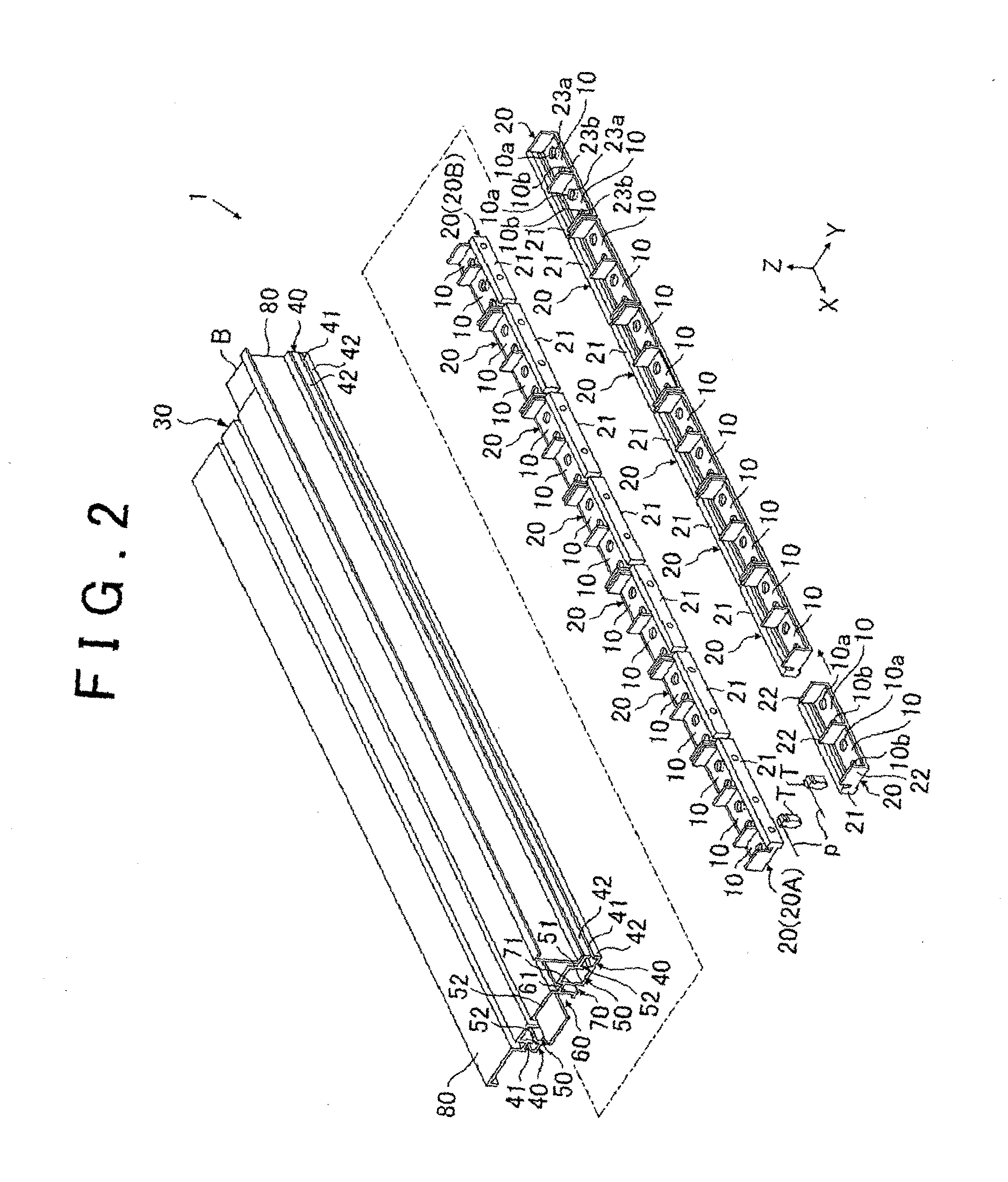
[0021](Embodiment 1) FIGS. 1 to 8 are views each illustrating Embodiment 1 of the present invention. FIG. 1 is a schematic perspective view of a connection unit and a battery pack. In FIG. 1 and so on, an X-axis, a Y-axis, and a Z-axis are axes perpendicular to each other. A relationship between the X-axis, the Y-axis, and the Z-axis is the same in the other drawings. In the present embodiment an axis corresponding to a vertical direction is regarded as the Z-axis.

[0022]As illustrated in FIG. 1, a connection unit 1 of the present embodiment is a connection member configured to electrically connect a plurality of single cells 3 aligned in an X-direction. Here, a battery pack 2 is constituted by the plurality of single cells 3.

[0023]The single cell (corresponding to a storage element) 3 includes a battery outer case 4 in which a power generation element is accommodated. The single cell 3 is a so-called square-shaped ...


PUM

PropertyMeasurementUnit
temperatureaaaaaaaaaa
voltageaaaaaaaaaa
lengthaaaaaaaaaa

Abstract

A connection unit of the present invention includes: a rail member extending in a direction where a plurality of storage elements is aligned; and a plurality of bus bar units each including an engagement portion movable along the rail member in the predetermined direction, and a bus bar fixed to electrode terminals of the storage elements adjacent to each other in the predetermined direction and connected to the engagement portion. The plurality of bus bar units engages with the rail member so as to be aligned in the predetermined direction, and the bus bar units adjacent to each other are provided so as to be movable independently along the predetermined direction. Entire assembly tolerance in the plurality of storage elements aligned in the predetermined direction can be absorbed (permitted) by adjusting distances between the independent bus bar units, thereby making it possible to easily assemble the plurality of bus bars.

Description

BACKGROUND OF THE INVENTION1. Field of the Invention[0001]The present invention relates to a connection unit configured to electrically connect a plurality of storage elements to each other.2. Description of Related Art[0002]A battery pack can be configured such that a plurality of single cells is aligned in a predetermined direction. At this time, the plurality of single cells is electrically connected to each other via a plurality of bus bars. Japanese Patent Application Publication No. 2012-243608 (JP 2012-243608 A) describes an integral bus bar module in which to accommodate a plurality of bus bar. The bus bar module includes bus bar accommodation portions configured to accommodate respective bus bars therein.[0003]The single cell has tolerance in dimension in a predetermined direction. Because of this, variations occur in length of the battery pack in the predetermined direction. Along with this, a bus bar connected to the single cell may be displaced in the predetermined direc...

Claims


Application Information

Patent Timeline
Patent Type & Authority Applications(United States)
IPC IPC(8): H01M2/20H01M2/10H01M2/12H01M10/48H01M50/209H01M50/505H01M50/569
CPCH01M2/206H01M10/486H01M2220/20H01M2/1241H01M10/48H01M2/1077Y02E60/10H01M50/3425H01M50/209H01M50/505H01M50/569
Inventor WATANABE, HIROTAKA
Owner TOYOTA JIDOSHA KK
Why Eureka
Try Eureka