Interconnector and solar panel

Inactive Publication Date: 2017-01-12
TOYOTA IND CORP +1
View PDF0 Cites 5 Cited by
  • Summary
  • Abstract
  • Description
  • Claims
  • Application Information

AI Technical Summary

Benefits of technology

[0008]It is an object of the present invention to provide an interconnector and a solar panel that reduce the occurrence of defective electrical connectio

Problems solved by technology

As a result, electrical connection between the first photovoltaic battery cell and the second photovoltaic battery cell may be impeded in th

Method used


Image

  • Interconnector and solar panel
  • Interconnector and solar panel
  • Interconnector and solar panel

Examples


Example

First Embodiment

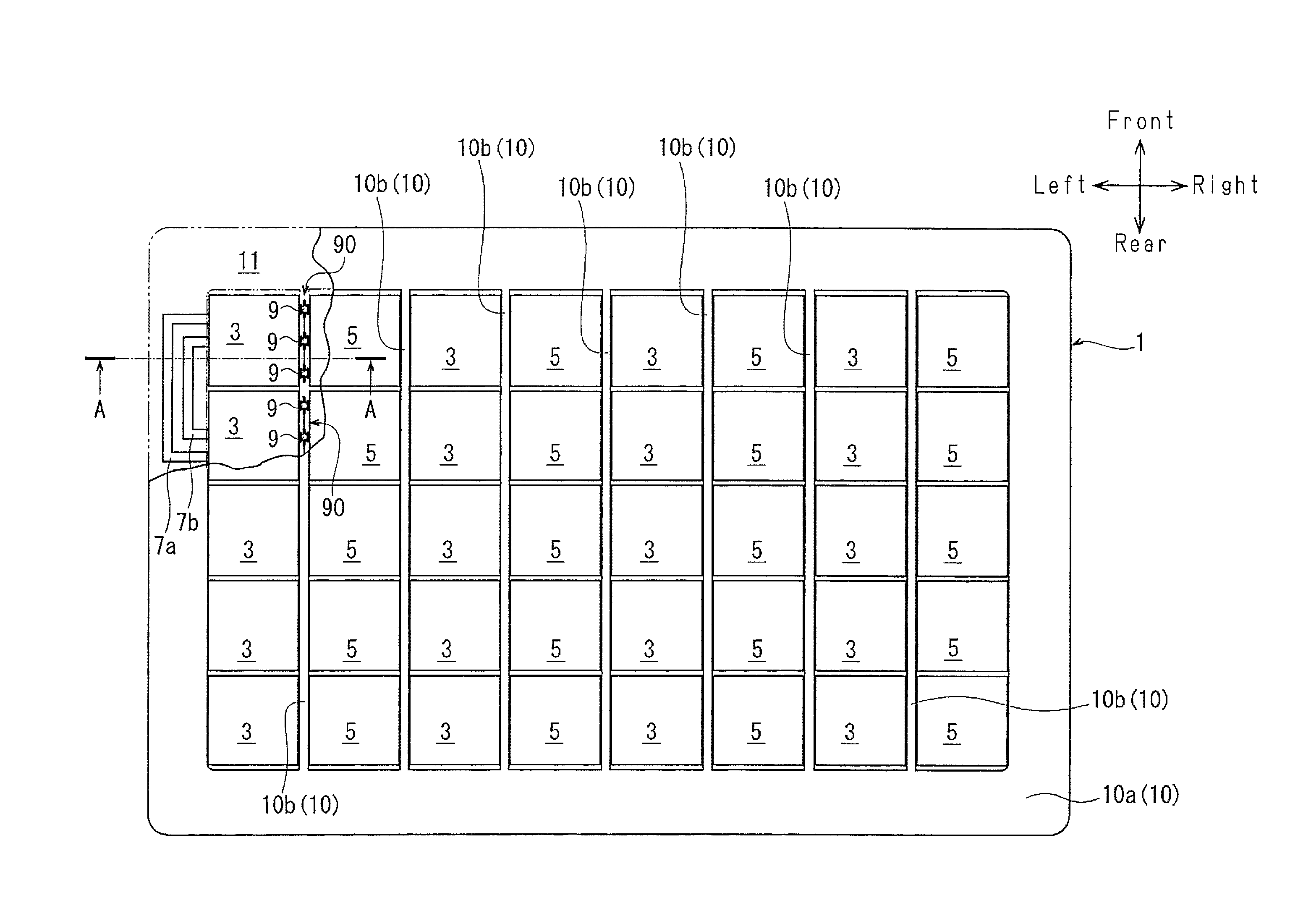
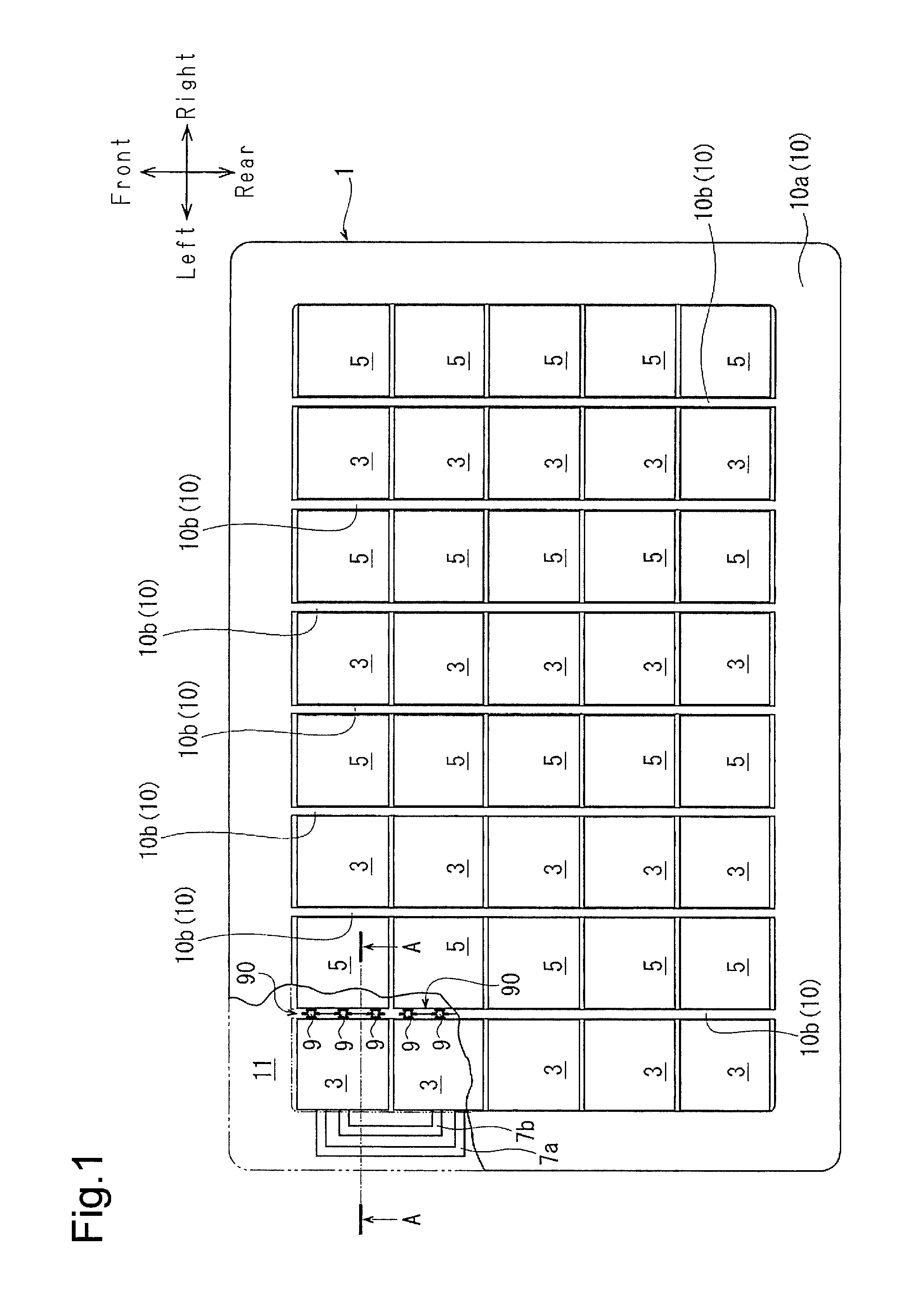
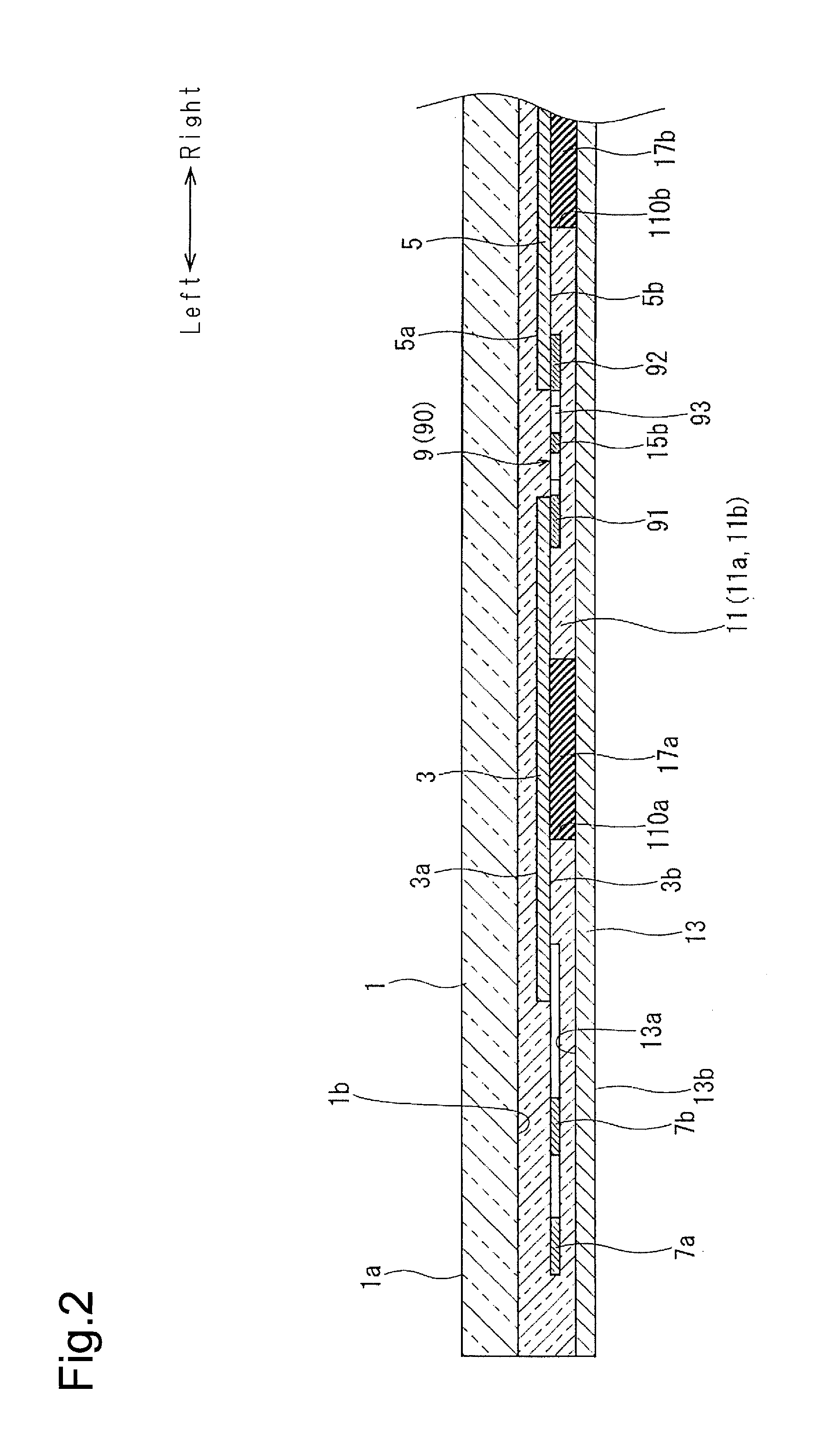
[0027]As shown in FIG. 1, a solar panel of the first embodiment includes a protection plate 1, first photovoltaic battery cells 3, second photovoltaic battery cells 5, tab wires 7a and 7b, interconnectors 9, an encapsulant 11, and a back panel 13, which is shown in FIG. 2. The protection plate 1 corresponds to a protection cover, and the back panel 13 corresponds to a back cover. To facilitate understanding, the protection plate 1 is not shown in the portion illustrated by broken lines in FIG. 1.

[0028]In the present embodiment, the arrows in FIG. 1 indicate the left, right, front, and rear directions of the solar panel. The direction extending from the left to the right is orthogonal to the direction extending from the front to the rear. The directions in the other drawings such as FIG. 2 correspond to the directions shown in FIG. 1, and the thickness-wise direction of the solar panel defines the vertical direction. The left-to-right (lateral) direction of the solar ...

Example

Second Embodiment

[0068]The solar panel of the second embodiment includes an interconnector 23 that is shown in FIG. 10 instead of the interconnector 9 of the solar panel of the first embodiment. The interconnector 23 is punched out of a copper plate. The number of the interconnectors 23 may be changed.

[0069]The interconnector 23 includes a first electrode 231, a second electrode 232, and a connection body 233. The first electrode 231 is located at the left side of the interconnector 23. The second electrode 232 is located at the right side of the interconnector 23. The first electrode 231 includes a first base 231a, which extends in the front-to-rear direction of the interconnector 23, and a first contact 231b, which is integrated with the first base 231a and extended from the first base 231a toward the left side. The second electrode 232 includes a second base 232a, which extends in the front-to-rear direction of the interconnector 23, and a second contact 232b, which is integrated...

Example

Third Embodiment

[0076]The solar panel of the third embodiment includes an interconnector 25 shown in FIG. 11 instead of the interconnector 9 of the solar panel of the first embodiment. The interconnector 25 includes a first electrode 26, a second electrode 27, and a connection body 28. The first electrode 26 and the second electrode 27 are punched out of a copper plate. The first electrode 26 is located at the left side of the interconnector 25, and the second electrode 27 is located at the right side of the interconnector 25. The first electrode 26 includes a first base 26a, which extends in the front-to-rear direction of the interconnector 25, and a first contact 26b, which is integrated with the first base 26a and extended from the first base 26a toward the left side. The second electrode 27 includes a second base 27a, which extends in the front-to-rear direction of the interconnector 25, and a second contact 27b, which is integrated with the second base 27a and extended from the...


PUM


Abstract

An interconnector includes a first electrode configured to be connected to a first photovoltaic battery cell, a second electrode configured to be connected to a second photovoltaic battery cell, and a connection body that connects the first electrode and the second electrode. The connection body includes a first detour portion, a second detour portion, and a first connection portion. The first detour is electrically connected to the first electrode and extended toward a first side in a second direction orthogonal to a first direction. The second detour is electrically connected to the second electrode and extended toward the first side in the second direction. The first connection portion extends toward the first detour portion and the second detour portion in the first direction and connects the first detour portion and the second detour portion.

Description

BACKGROUND OF THE INVENTION[0001]The present invention relates to an interconnector and a solar panel.[0002]Japanese Laid-Open Patent Publication No. 2005-191479 discloses a conventional solar panel including a protection cover, a back cover, a first photovoltaic battery cell, a second photovoltaic battery cell, an interconnector, and an encapsulant.[0003]The protection cover is formed from inorganic glass and is translucent from the front surface to the rear surface. The back cover is formed by a resin film or the like. The first photovoltaic battery cell and the second photovoltaic battery cell are adjacent to each other in a first direction.[0004]The interconnector is flat. The interconnector is arranged to be horizontal to the first photovoltaic battery cell and the second photovoltaic battery cell between the first photovoltaic battery cell and the second photovoltaic battery cell. The interconnector includes a first electrode connected to the first photovoltaic battery cell, a...

Claims


Application Information

Patent Timeline
IPC IPC(8): H02S40/34H01L31/048H01L31/049H02S40/38
CPCH02S40/34H01L31/049H01L31/0488H02S40/38H01L31/0508Y02E10/50Y02E70/30
Inventor INABA, HIROTAKAKIMURA, KAZUTAKA
Owner TOYOTA IND CORP
Why Eureka
Try Eureka