Application method and film

a technology which is applied in the field of application method and film, can solve the problems of excessive crease of film, affecting the quality of film application, and generating shock lines in the film, so as to achieve the effect of improving the application quality of the film

Active Publication Date: 2017-01-19
3M INNOVATIVE PROPERTIES CO
View PDF7 Cites 8 Cited by
  • Summary
  • Abstract
  • Description
  • Claims
  • Application Information

AI Technical Summary

Benefits of technology

[0015]According to one aspect of the present invention, the application quality of the film can be improved.

Problems solved by technology

However, in such work of pressing, or a process of applying, the film to the base material, there is a concern that a shock line will be generated in the film, which would be aesthetically undesirable.
The possibility of such a shock line being generated exists over the entire process of film application, including at a pressing start location and a pressing end location; in particular, when applying a film of a high gloss, a crease thereof standing out excessively has been regarded as a problem.

Method used


Image

  • Application method and film
  • Application method and film
  • Application method and film

Examples


first exemplary embodiment

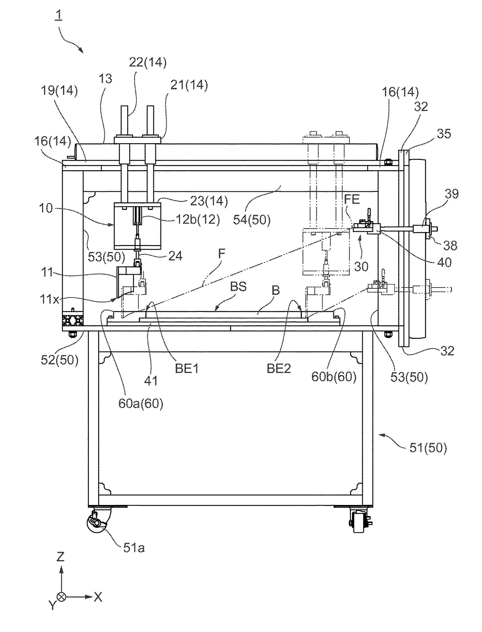
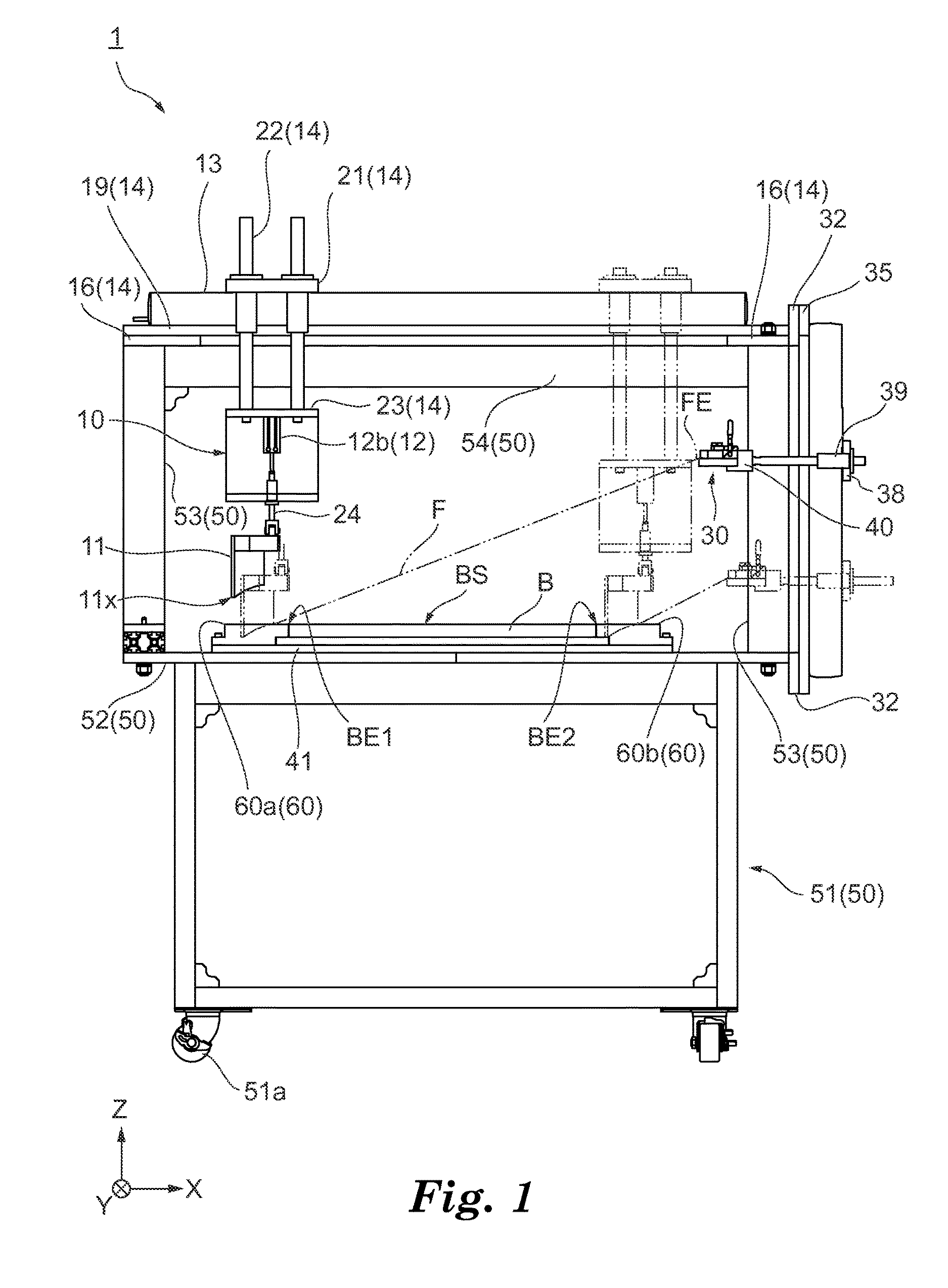
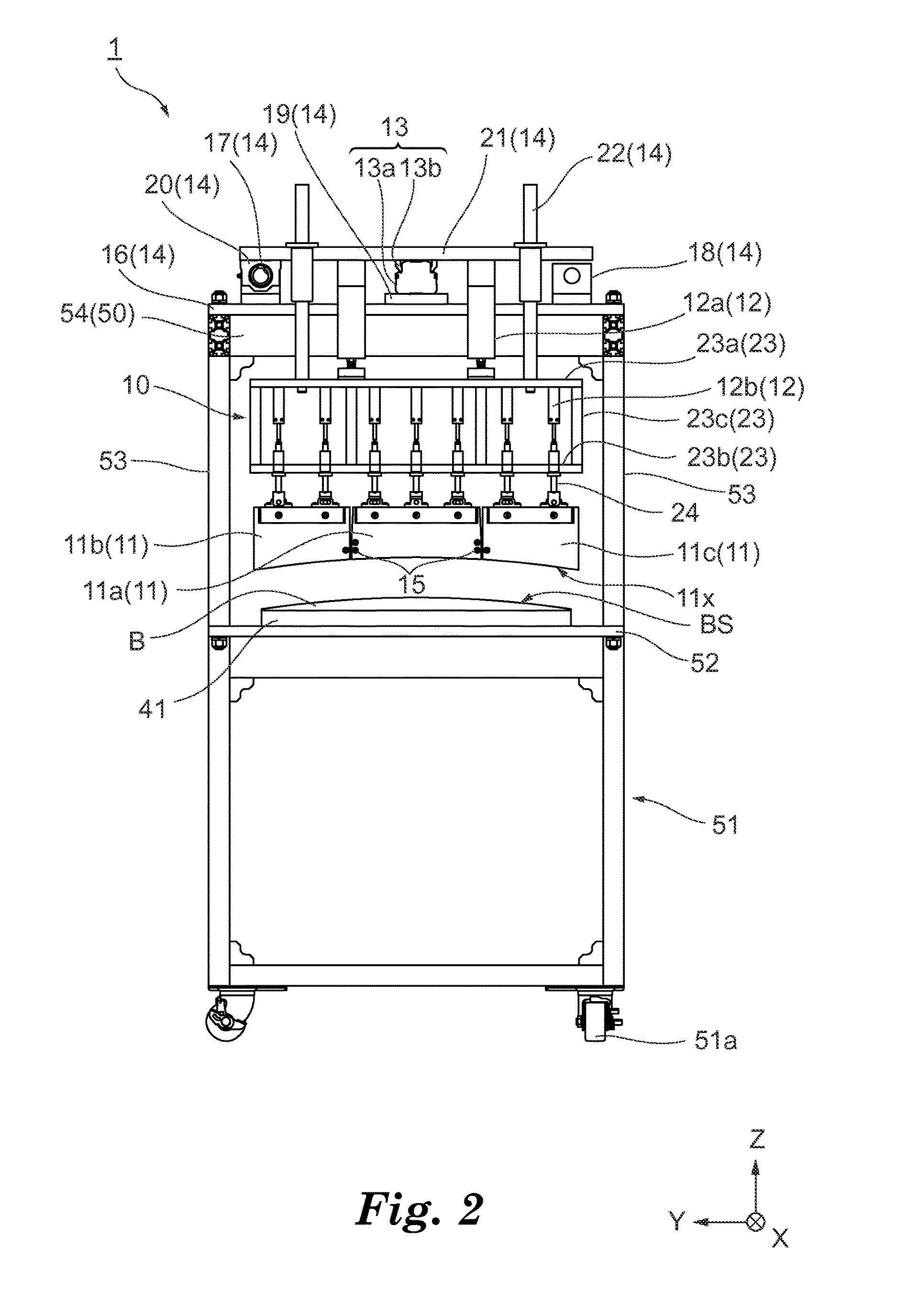
[0028]A configuration of an application device 1 relating to a film and an application method of the film of the first embodiment will be described with reference to FIGS. 1 to 3. The application device 1 is an application device that applies a film F onto a base material B having a bonding surface BS. The base material B having the bonding surface BS is not particularly limited as long as it is a base material having a surface to which the film F is applied. The base material B utilized in this embodiment has the bonding surface BS that is curved so as to be convex upward and has a horizontal cross-sectional shape that is constant in the length direction. The film F is not particularly limited as long as it has a thin film shape and is molded in a thin film shape having a polymer component such as a synthetic resin and the like. Details of the film F will be described below.

[0029]First, a frame structure 50 of the application device 1 will be described. As illustrated in FIG. 1 to ...

second exemplary embodiment

[0065]A film according to a second embodiment will be described with reference to FIGS. 1 to 6 as well as FIG. 7. As illustrated in FIG. 7A, a film FX is, similarly to the film F according to the first embodiment, provided with: a main portion 81 of a rectangular shape; an extended portion 82 (first extended portion) of a trapezoidal shape continuously connected to a first end 81x in a longitudinal direction of the main portion 81 (end portion on the X-axis direction negative side in the main portion 81); and an extended portion 83 (second extended portion) of a trapezoidal shape continuously connected to a second end 81y in the longitudinal direction of the main portion 81 (end portion on the X-axis direction positive side in the main portion 81). Near both ends in the X-axis direction of the film FX, hole portions 87 to be fitted to the projecting portion 31x are formed. In other words, near an end portion 83x of the extended portion 83, a hole portion 87y to be fitted to the proj...


PUM

PropertyMeasurementUnit
pressing forceaaaaaaaaaa
pressureaaaaaaaaaa
pressure sensitiveaaaaaaaaaa

Abstract

An application method of applying a film F having a main portion 71, an extended portion 72 connected to a first end 71x of the main portion 71, and an extended portion 73 connected to a second end 71y opposing the first end 71x in the main portion 71 to a base material by an application device having an application mechanism, including the steps of: pressing the extended portion 72 using the application mechanism; applying the main portion 71 to the base material by moving the application mechanism that presses the extended portion 72 from the extended portion 72 to the extended portion 73 via the main portion 71; and stopping the application mechanism moved to the extended portion 73 and separating the application mechanism from the extended portion 73.

Description

FIELD OF THE INVENTION[0001]One form of the present invention relates to a method of applying a film to relatively wide surfaces, and to a film such as, e.g., an adhesive-backed film.BACKGROUND ART[0002]For example, as described in Japanese Unexamined Patent Application Publication No. 2000-160115A, an adhesive-backed film may be applied to a surface of a predetermined base material. In recent years, there has been a demand to apply adhesive-backed film to surfaces of wide base materials having all kinds of shapes (for example, a film for replacing liquid paint applied to a roof of a vehicle, appliance or the like). The work to apply this type of film is commonly performed manually using a squeegee type tool (may be described below simply as a squeegee) that mounts a rubber blade on the tip end.SUMMARY OF THE INVENTION[0003]When performing the work to apply a film (e.g., an adhesive-backed film) on a surface of a base material using a squeegee, it is necessary to press the film agai...

Claims


Application Information

Patent Timeline
Patent Type & Authority Applications(United States)
IPC IPC(8): B32B37/10B32B37/12B32B7/12B29C65/48
CPCB32B37/10B29C65/4825B32B37/12B32B2307/412B32B2605/003B29L2031/3011B32B7/12B65B33/04C09J2433/00C09J2301/302B29C63/0004B29C63/02B29C2063/027B29L2031/3055
Inventor KUBOTA, MASAYUKITOKUNAGA, TAISHIFUJINO, TAKAYOSHISAKAI, KATSUNORIWAKAMATSU, HIROKI
Owner 3M INNOVATIVE PROPERTIES CO
Why Eureka
Try Eureka