Moving crane

a technology of moving cranes and cranes, which is applied in the direction of cranes, load-engaging elements, transportation and packaging, etc., can solve the problems of difficult to notice any essential change, difficult to detect a depth difference of 0-0.5 m between a container and the upper surface of a trailer, etc., to improve the weight distribution of the crane, easy to bring, and simple to opera

Inactive Publication Date: 2017-01-19
KONECRANES GLOBAL
View PDF18 Cites 6 Cited by
  • Summary
  • Abstract
  • Description
  • Claims
  • Application Information

AI Technical Summary

Benefits of technology

[0013]The cab may also be built in a light-weight manner whenever there is the option to build separate stiffening steel structures outside of it, in case a container should become loose during a hoist, to prevent the operator from getting squeezed. Stiffening steel structures, that is, safety structures, are more economical to construct than to make the cab stiff, in particular as regards a load falling on it. The stiffeners may be placed in front of and / or obliquely above the cab.
[0014]Similarly, when the hoisting mechanism is also located close to the ground level in connection with the other lower beam structure, it is possible to place them close to the main power source, making electrisation simpler and improving the weight distribution of the crane. Items in need of servicing are more easily available and the necessary spare parts can be easily brought thereto by means of a fork-lift truck, for instance. When the control cabin thus at the same time remains in connection with the lower beam structure located on a side opposite to the crane, the control cabin is situated far away from the sources of noise and vibration. Further, an optimum protection of the cab and operator from exhaust noise is achieved as exhaust fumes are directed substantially straight up, whereby the exhaust port of the exhaust pipe may be placed as far away from the operator as possible. While handling a load, when the container is lowered or lifted substantially at the level of the cab, the container itself forms a temporary noise wall between the machine unit and the cab.
[0015]When the machinery and the cab are moved from the trolley to be located close to the ground level, the trolley becomes light in structure, enabling also the support structure of the crane to be made lighter. At the same time, of course, the centre of gravity of the crane becomes to be situated lower, stabilizing the travel of the crane. Also, fewer passageways and platforms are required in the upper part when no emergency exits are necessary from top to bottom in case of fires or other accidents.
[0016]The parts of the crane are designed such that they can be packed and transported as modules in containers to the installation site. This makes the transportation easier to plan, when no large structural steel parts and components have to be transported separately as general cargo. The main support structure and the legs are built from interconnectable beam parts to be interconnected at the installation site. The rest of the parts are designed in a similar manner so as to be packed in containers. Packing in containers provides advantages in logistics whereby energy will be saved when examining the issue as a whole. The effects caused by the weather are diminished, and transporting as well as packing are simplified.
[0017]From the point of view of the total energy usage of a yard gantry crane, the carbon footprint is lower than with prior art solutions as the design of the machinery, cabling, and energy usage are reduced by counterweights, in addition to the aforementioned logistics advantages. The amount of energy used for manufacturing is smaller and the assembly of the device from modules at the delivery site is simple.

Problems solved by technology

Earlier, the working position in a cab placed high up was awkward and strained the support and movement organs: an operator is continuously sitting in a forward stooped position and looking straight down between his spread out legs.Easier loading and unloading on truck lanes, the operator sees the lowering / hoisting operation from the side and from the right height as a container goes down on or up from a trailer.
In prior art, the operator sees the lowering / hoisting situation from high above whereby it is difficult to detect a depth difference of 0-0.5 m between a container and the upper surface of a trailer.
The hoisting capacity of a crane is so big that it is difficult to notice any essential change in the hoisting power when hoisting an empty or partially filled container, as seen from above, if the container is not fully disconnected from the corner locks that keep the container in place, in other words, it is possible to lift a truck's trailer by accident.

Method used


Image

  • Moving crane
  • Moving crane

Examples


Embodiment Construction

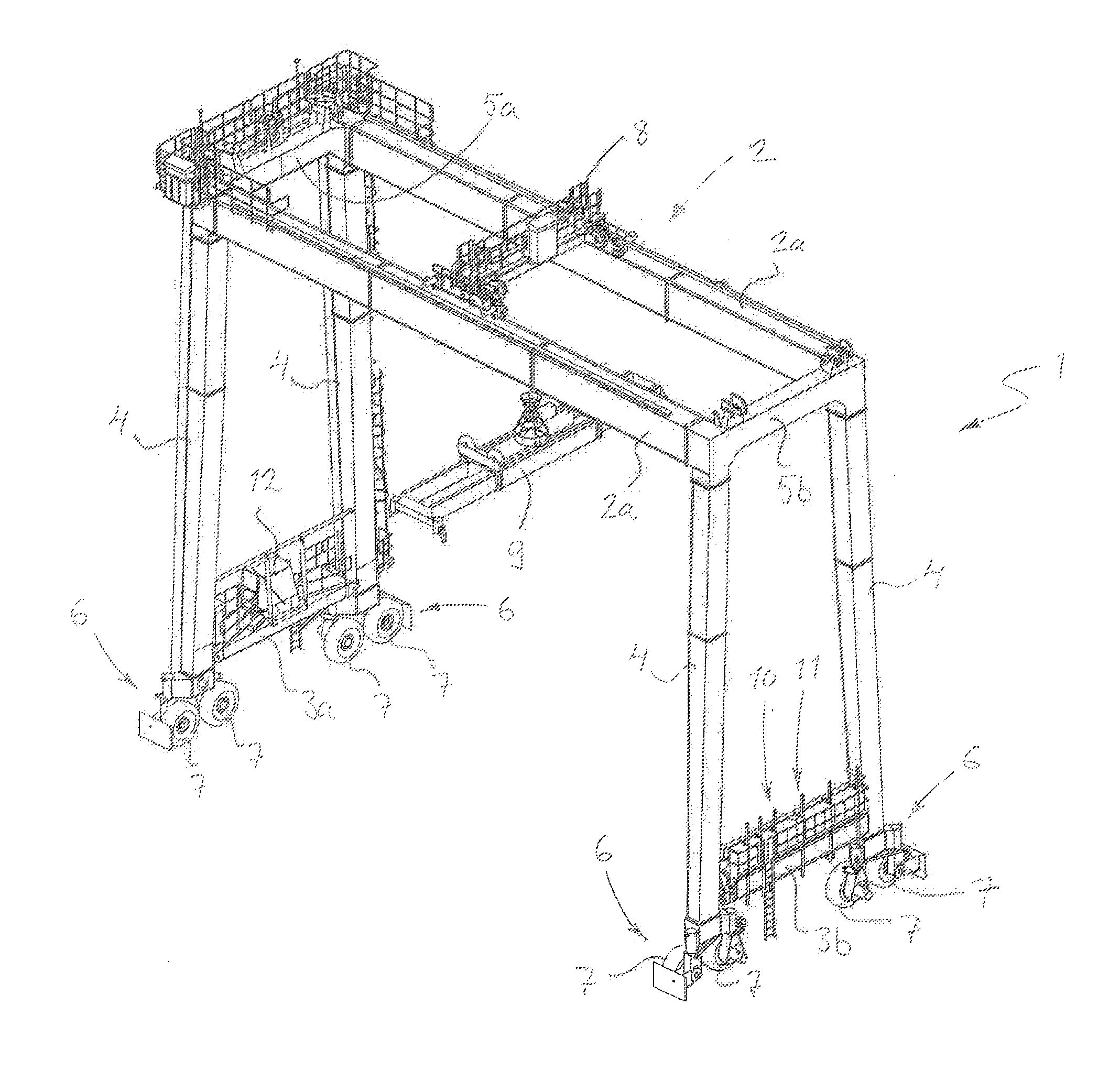
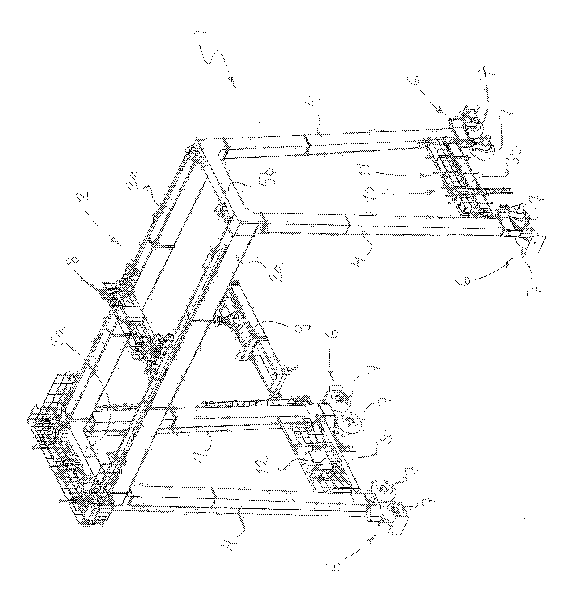
[0019]Referring to the FIGURE, a moving crane according to the invention has a frame 1 which, in its upper part, is provided with a main support structure 2 and which, in its lower part and on opposite sides of the lower part of the frame 1, is provided with lower beam structures 3a and 3b transverse to the main support structure 2. The main support structure 2 is connected to the lower beam structures 3a and 3b by upright legs 4. The main support structure 2 herein comprises two main supports 2a travelling, spaced apart from one another, parallelly and connected to one another by upper beam structures 5a and 5b.

[0020]The ends of the lower beam structures 3a and 3b are provided with bogie structures 6, each comprising two successive wheels 7. The total number of bogie structures 6 is thus four, one in each lower corner of the crane. In this example, the wheels are rubber wheels and, typically, one of the wheels 7 of each bogie 6 is a drive wheel while the other is a driven wheel. I...


PUM


Abstract

A moving crane including a frame which, in its upper part, is provided with a main support structure and which, in its lower part and on opposite sides of the lower part of the frame, is provided with lower beam structures transverse to the main support structure; at least one wheel or wheel arrangement at both ends of the lower beam structures, i.e. in each lower corner of the crane; a trolley arranged to move along the main support structure and provided with a hoisting member; a hoisting mechanism for driving the hoisting member of the trolley, and a cab for the crane operator, whereby the cab is placed in connection with one lower beam structure and the hoisting mechanism in connection with the other lower beam structure.

Description

FIELD OF THE INVENTION[0001]The invention relates to a moving crane comprising a frame which, in its upper part, is provided with a main support structure and which, in its lower part and on opposite sides of the lower part of the frame, is provided with lower beam structures transverse to the main support structure; at least one wheel or wheel arrangement at both ends of the lower beam structures, i.e. in each lower corner of the crane; a trolley arranged to move along the main support structure and provided with a hoisting member; a hoisting mechanism for driving the hoisting member of the trolley; and a cab for the crane operator.[0002]Such yard gantry cranes for storage areas in container terminals are designed for arranging and handling containers in a container storage yard. They move along paths parallel with container rows, either on rails or rubber wheels.[0003]Typically, the cab and hoisting mechanism of such a crane are located in a trolley moving on top of the main suppo...

Claims


Application Information

Patent Timeline
Patent Type & Authority Applications(United States)
IPC IPC(8): B66C19/00B66C13/18B66C13/16B66C13/54
CPCB66C19/007B66C13/16B66C13/18B66C13/54B66C19/00
Inventor OJAPALO, ESASANTALA, JUHAOJA, HANNU
Owner KONECRANES GLOBAL
Why Eureka
Try Eureka