
Seal runner with controlled oil lubrication

a technology of oil lubrication and seal runner, which is applied in the direction of engine seals, machines/engines, engine fuctions, etc., can solve the problems of affecting the ability of a bearing compartment to contain oil, contacting, and increased air leakage characteristics,

Active Publication Date: 2017-01-19
RAYTHEON TECH CORP
View PDF4 Cites 16 Cited by
  • Summary
  • Abstract
  • Description
  • Claims
  • Application Information

AI Technical Summary

Benefits of technology

The present patent relates to a sealing arrangement for an engine of an aircraft. The arrangement includes a ring, a runner, and a hole that supplies oil to the interface between the ring and the runner. The oil is collected by an annulus and conveyed to the interface through a radially-oriented hole in the ring. The arrangement allows for efficient oil supply to the interface, and includes options for controlling the oil flow and preventing leakage. The technical effects of this arrangement include improved sealing performance and reduced oil leakage, which can prolong the life of the engine and improve its efficiency.

Problems solved by technology

Experience has demonstrated elevated seal wear and seal runner distress / deterioration, which results in increased air leakage characteristics and impacts the ability of a bearing compartment to contain oil.
A contacting, dry running seal can be limited by the capabilities of the materials selected.
At elevated rubbing velocities, testing and experience have demonstrated that available materials are not able to withstand these conditions.
Alternate solutions that have the high rubbing velocity capability, such as clearance seals (Knife Edge Lab, Controlled Gap, etc.) and Lift-Off Seals, present unique risks; system requirements may prevent their utilization.

Method used


Image

  • Seal runner with controlled oil lubrication
  • Seal runner with controlled oil lubrication
  • Seal runner with controlled oil lubrication

Examples


Embodiment Construction

[0025]It is noted that various connections are set forth between elements in the following description and in the drawings (the contents of which are included in this disclosure by way of reference). It is noted that these connections are general and, unless specified otherwise, may be direct or indirect and that this specification is not intended to be limiting in this respect. A coupling between two or more entities may refer to a direct connection or an indirect connection. An indirect connection may incorporate one or more intervening entities.

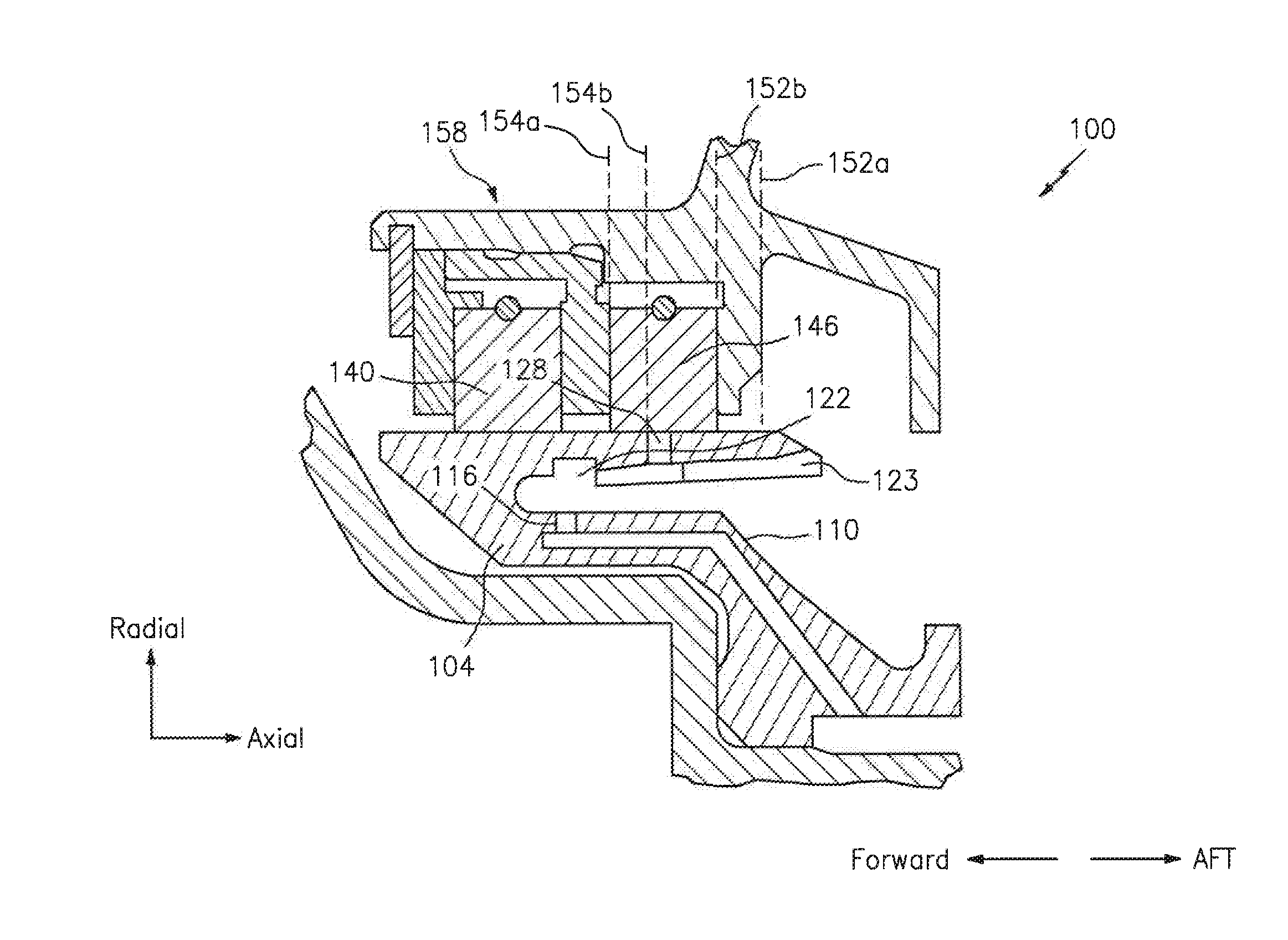
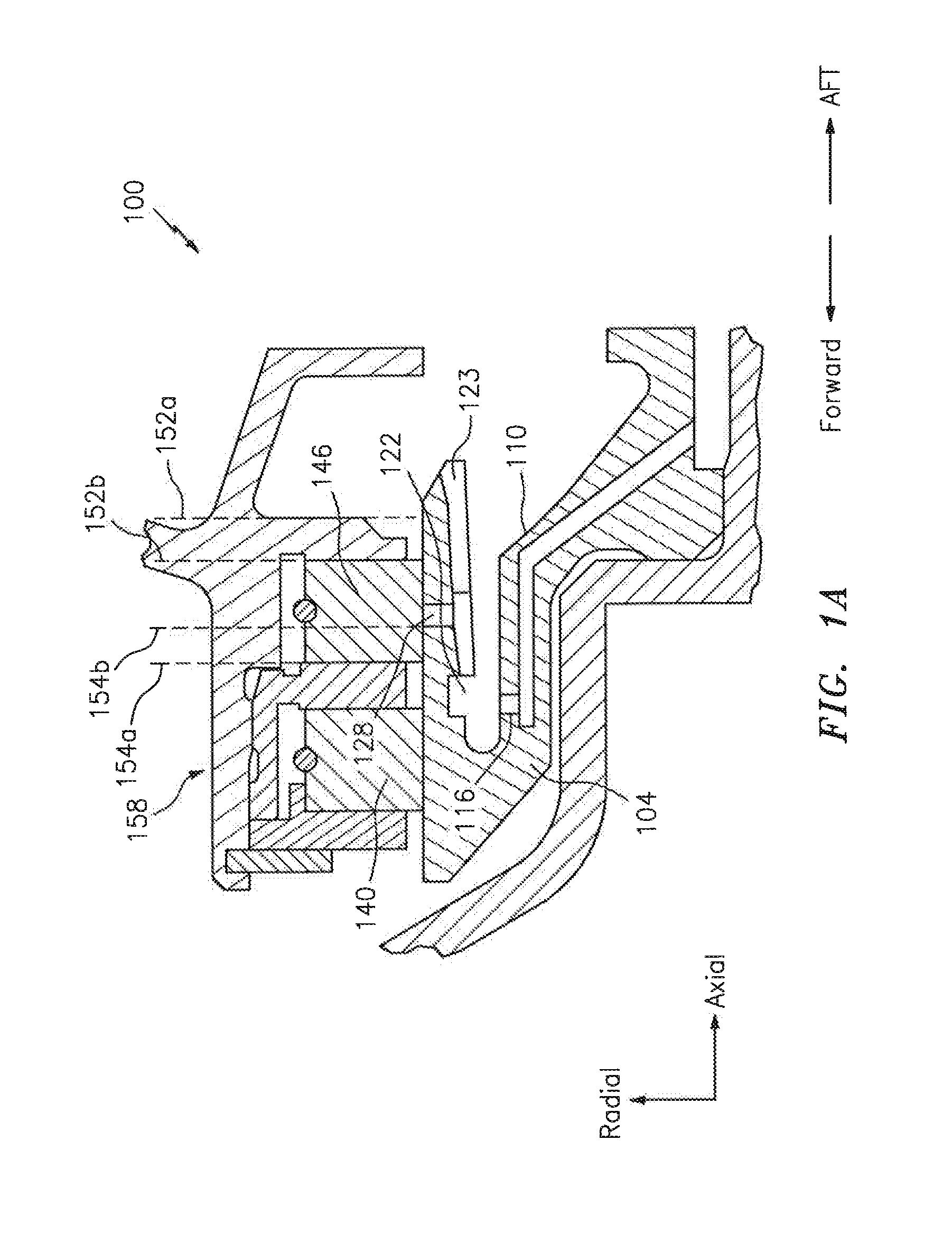
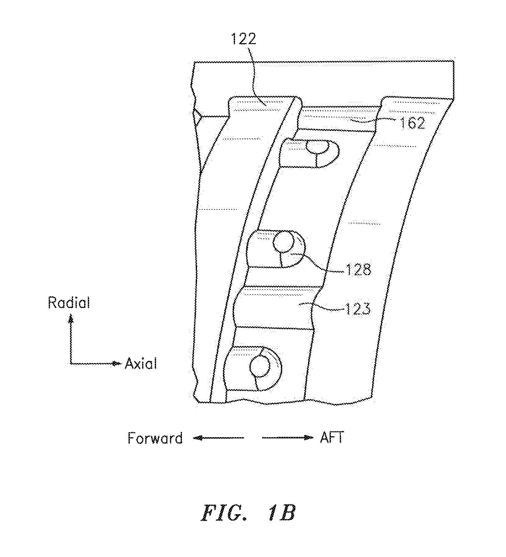
[0026]In accordance with various aspects of the disclosure, apparatuses, systems and methods are described for providing a seal or seal runner with a controlled sealing interface. In some embodiments, a radial seal or associated seal runner may be provided or utilized. The sealing interface may facilitate sealing with respect to one or more fluids, such as for example oil that is used in lubricating a bearing.

[0027]Aspects of the disclosur...


PUM


Abstract

A system is provided associated with an engine of an aircraft. The system includes a ring, a runner and at least one radially-oriented hole associated with the runner that is configured to supply oil to an interface between the runner and the ring. The at least one hole is contained within an axial projection of the ring.

Description

BACKGROUND[0001]Advanced, high-performance engines will require improved performance main shaft bearing compartment seals while also being required to meet more aggressive cost, weight, size, environmental and reliability metrics. Carbon seals may be manufactured to enable an engine and bearing compartment to function with minimal impact on Thrust Specific Fuel Consumption (TSFC), Thermal Management Systems (TMSs) and Lubrication Systems. Advanced engines require seals with improved wear resistance, improved performance, and improved reliability in order to meet customer, user, or program metrics.[0002]Experience has demonstrated elevated seal wear and seal runner distress / deterioration, which results in increased air leakage characteristics and impacts the ability of a bearing compartment to contain oil. Future engines may experience elevated rubbing velocities relative to existing engine platforms, which could demand alternate solutions. A contacting, dry running seal can be limit...

Claims


Application Information

Patent Timeline
IPC IPC(8): F01D25/18F01D11/00F01D5/02
CPCF01D25/183F01D5/02F05D2240/60F05D2220/323F01D11/005F01D11/003F01D25/166F01D25/186F05D2260/98F05D2240/581F16J15/441F16J15/324F16J15/40
Inventor MILLER, JONATHAN L.ULLAH, M. RIFAT
Owner RAYTHEON TECH CORP
Learn More