Pressure buffer device and damping force generating member
- Summary
- Abstract
- Description
- Claims
- Application Information
AI Technical Summary
Benefits of technology
Problems solved by technology
Method used
Image

Examples
first embodiment
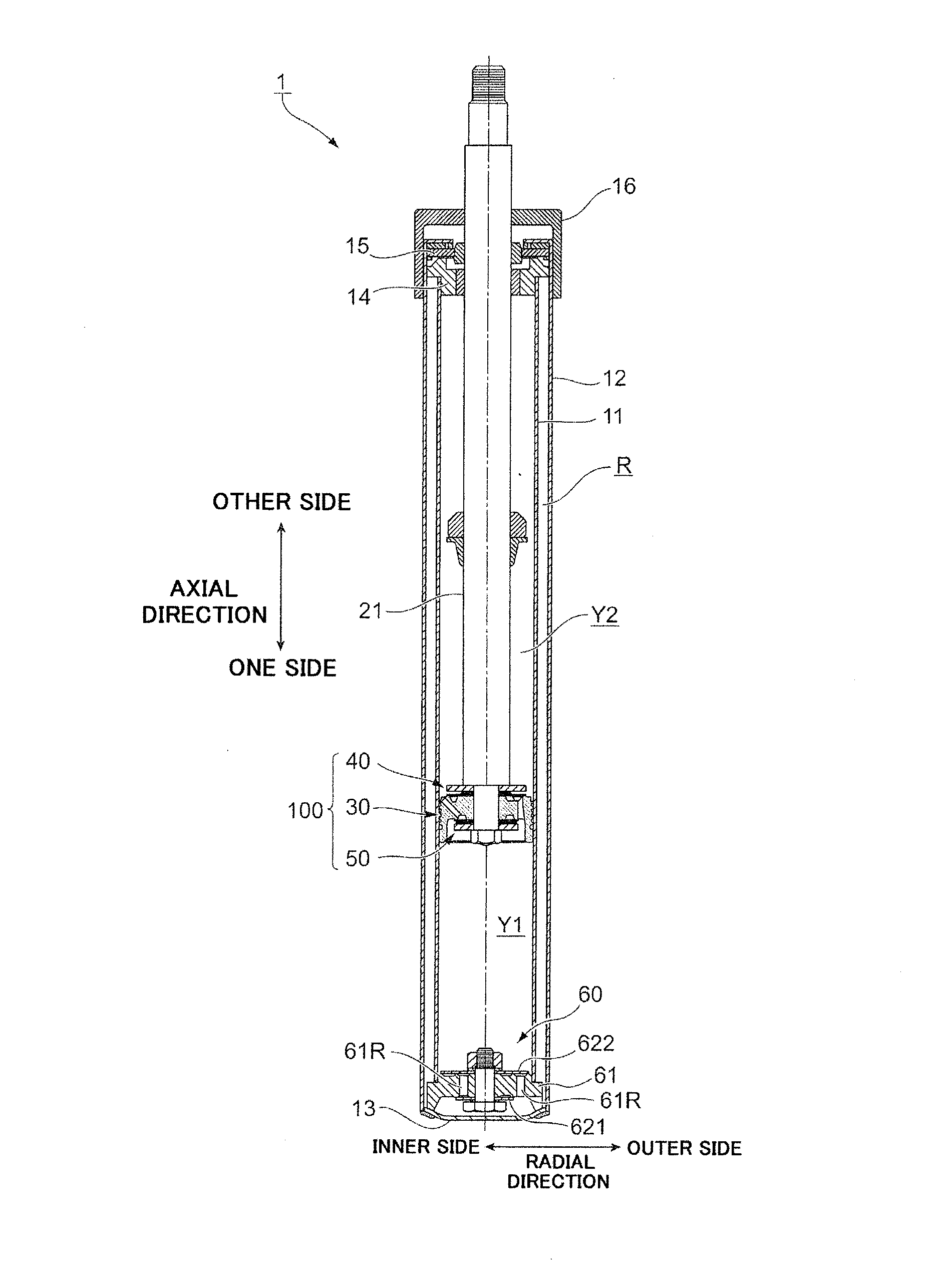
[0031]FIG. 1 is an overall structural view of a hydraulic buffer device 1 of a first embodiment.
[0032]In the following description, the longitudinal direction of the hydraulic buffer device 1 illustrated in FIG. 1 is referred to as “an axial direction”. In the axial direction, the lower side of the hydraulic buffer device 1 is referred to as “one side” and the upper side of the hydraulic buffer device 1 is referred to as “the other side”. The lateral direction of the hydraulic buffer device 1 illustrated in FIG. 1 is referred to as “a radial direction”, while a side toward the center axis side and a side away from the center axis are referred to as “an inner side” and “an outer side”, respectively.
[Configuration of Hydraulic Buffer Device 1]
[0033]First, a configuration of the hydraulic buffer device 1 of the first embodiment is described.
[0034]As illustrated in FIG. 1, the hydraulic buffer device 1 of the first embodiment includes a first cylinder 11 that stores oil, a second cylind...
second embodiment
[0087]Next, a hydraulic buffer device 1 of a second embodiment will be described.
[0088]FIG. 5 illustrates a piston body 230 of the second embodiment.
[0089]FIG. 5A is a top view of the piston body 230 viewing from the other side, FIG. 5B is a sectional view at Vb-Vb of the piston body 230 illustrated in FIG. 5A, and FIG. 5C is a partial perspective view of the piston body 230 viewing from the other side.
[0090]In the description of the second embodiment, the same reference is provided to the same structural element as the abovementioned first embodiment and detailed description thereof is skipped.
[0091]As illustrated in FIGS. 5A to 5C, the piston body 230 of the second embodiment includes the through-hole 31, the first compression-side oil path 32, the first extension-side oil path 33, the inner annular section 34, the extending section 35, the outer annular section 36, the one-side inner annular section 37, the one-side outer annular section 38, and a projecting section 239 arranged ...
first modification example
[0097]FIG. 6 illustrates a modification example (first modification example) of the piston body 230 of the second embodiment.
[0098]As illustrated in FIG. 6A, in the piston body 230 of the second embodiment, the projection height of the extending section 35 may be lower than that of the inner annular section 34.
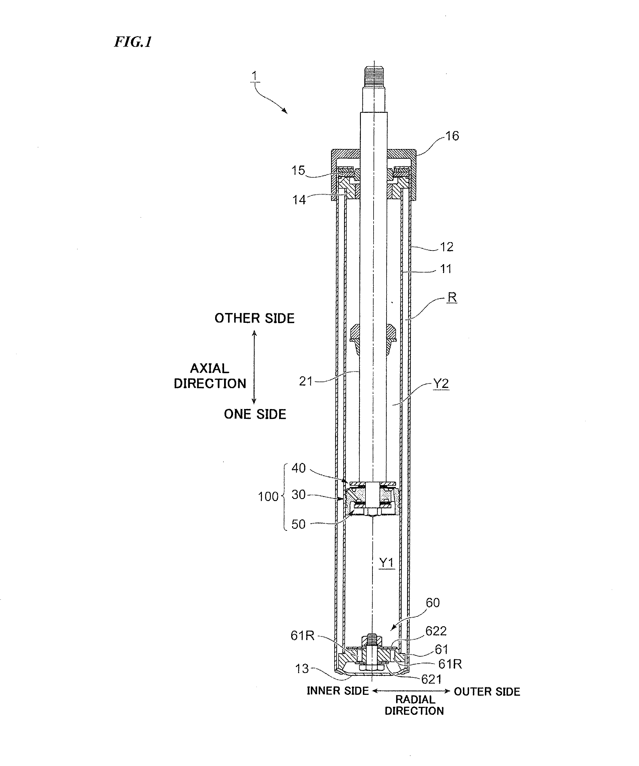
[0099]According to the piston body 230 of the modification example illustrated in FIG. 6A, since the projection height of the extending section 35 is lower than that of the inner annular section 34, there is formed a gap between the extending section 35 and the compression-side first valve 41 (see FIG. 2B) arranged on the other side. Owing to that oil enters to the gap between the extending section 35 and the compression-side first valve 41, sticking of the compression-side first valve 41 to the extending section 35 is suppressed and operation of the compression-side first valve 41 is stabilized. Consequently, variation of damping force to be generated in the hydraulic buffer ...
PUM
 Abstract
Description
Claims
Application Information
 - Generate Ideas
- Intellectual Property
- Life Sciences
- Materials
- Tech Scout
- Unparalleled Data Quality
- Higher Quality Content
- 60% Fewer Hallucinations
Browse by: Latest US Patents, China's latest patents, Technical Efficacy Thesaurus, Application Domain, Technology Topic, Popular Technical Reports.
© 2025 PatSnap. All rights reserved.Legal|Privacy policy|Modern Slavery Act Transparency Statement|Sitemap|About US| Contact US: help@patsnap.com