Device for Measuring Surface Speed and Liquid Level of Fluid

a technology of liquid level and surface speed, applied in the direction of instruments, machines/engines, using reradiation, etc., can solve the problems of reducing the processing speed of the whole measure system, signal integration and synchronization of time sequence, and restricted space and location choices, etc., to facilitate data transmission. , the effect of synchronization

Inactive Publication Date: 2017-01-19
U&U ENG
View PDF3 Cites 16 Cited by
  • Summary
  • Abstract
  • Description
  • Claims
  • Application Information

AI Technical Summary

Benefits of technology

[0015]Compared with the prior art, the device proposed by the present invention integrates the flow meter and the level gauge. The device reduces an occupied room, integrates time sequence of measurement of water flows and water levels, and facilitates a synchronization of data transmission. The device itself can measure water flows and water levels at the same time.

Problems solved by technology

It is often restricted to space and choices of location when the conventional measure system is installed.
Except the restrictions of quantity and installation, problems such as signal integration and synchronization of time sequence also occur in the conventional measure system.
Such problems often cause time sequence of information concerning water flows and water levels to be ahead of schedule or to be behind schedule.
So each flow meter and each level gauge adopts different interfaces (such as RS-232 or RS-485) for gathering signals, which greatly reduces the processing speed of the whole measure system.
Plus, because of asynchronous time sequence, the correlation and dependability of the data measured by the whole measure system cannot be accurately evaluated.

Method used


Image

  • Device for Measuring Surface Speed and Liquid Level of Fluid
  • Device for Measuring Surface Speed and Liquid Level of Fluid
  • Device for Measuring Surface Speed and Liquid Level of Fluid

Examples


Embodiment Construction

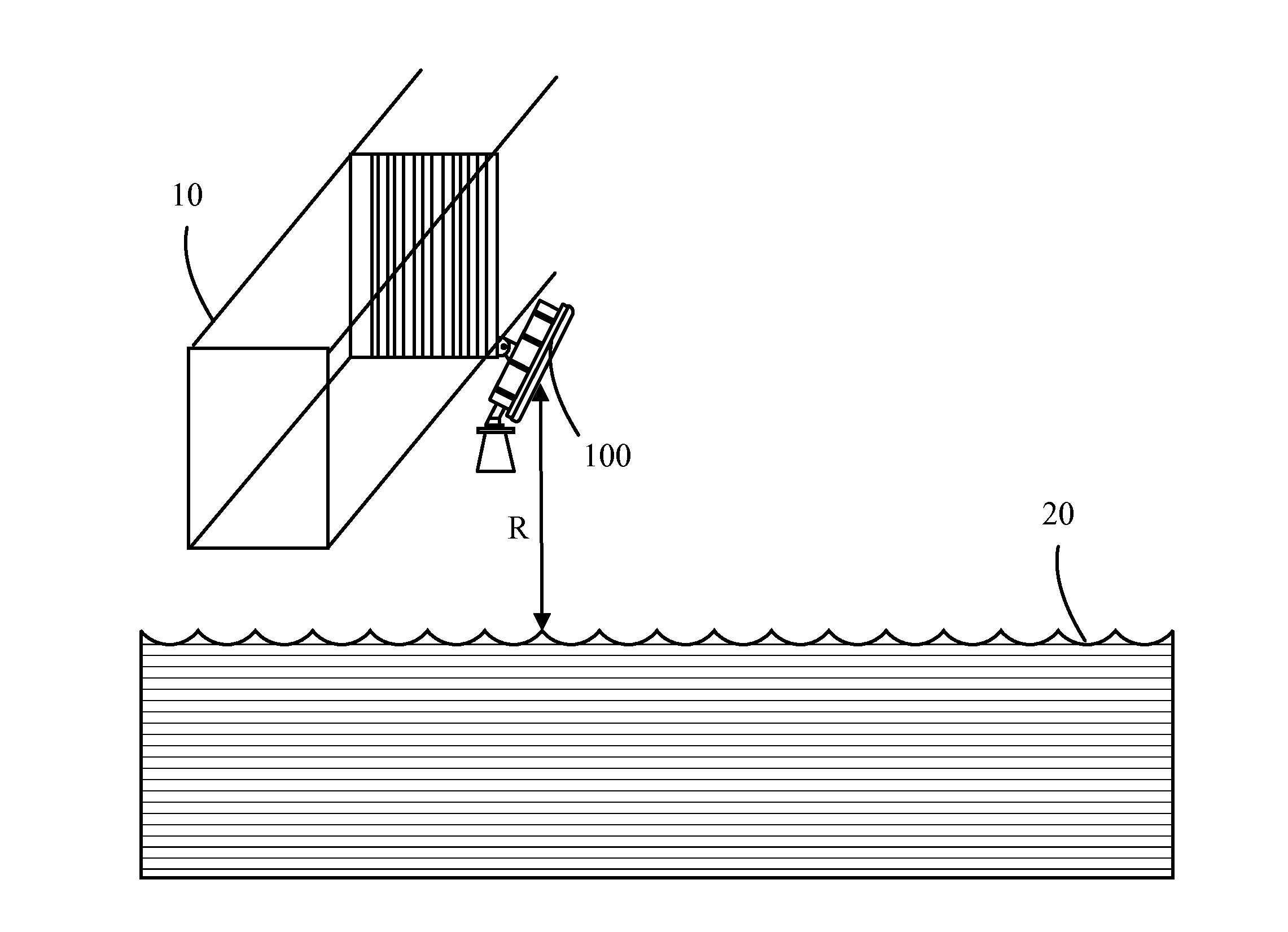
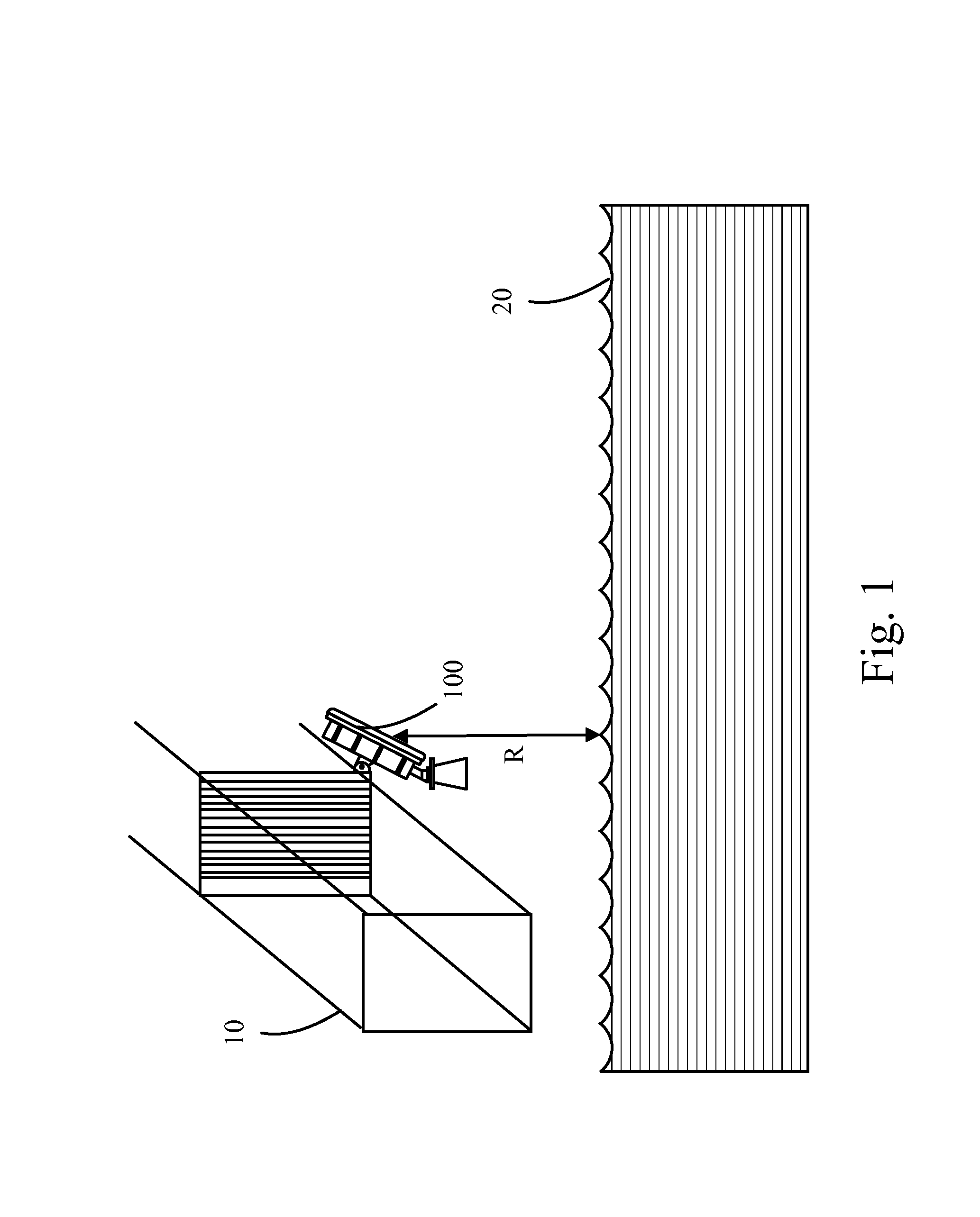
[0022]Please refer to FIG. 1 and FIG. 2. FIG. 1 is a schematic diagram of a measuring device 100 installed on a bridge 10 according to an embodiment of the present invention. FIG. 2 is a functional block diagram of the measuring device 100. The measuring device 100 is installed above a fluid 20 for measuring a surface speed and a water level of the fluid 20. Typically, the measuring device 100 can be disposed on the bridge 10 stretching over the fluid 20 (such as a river).

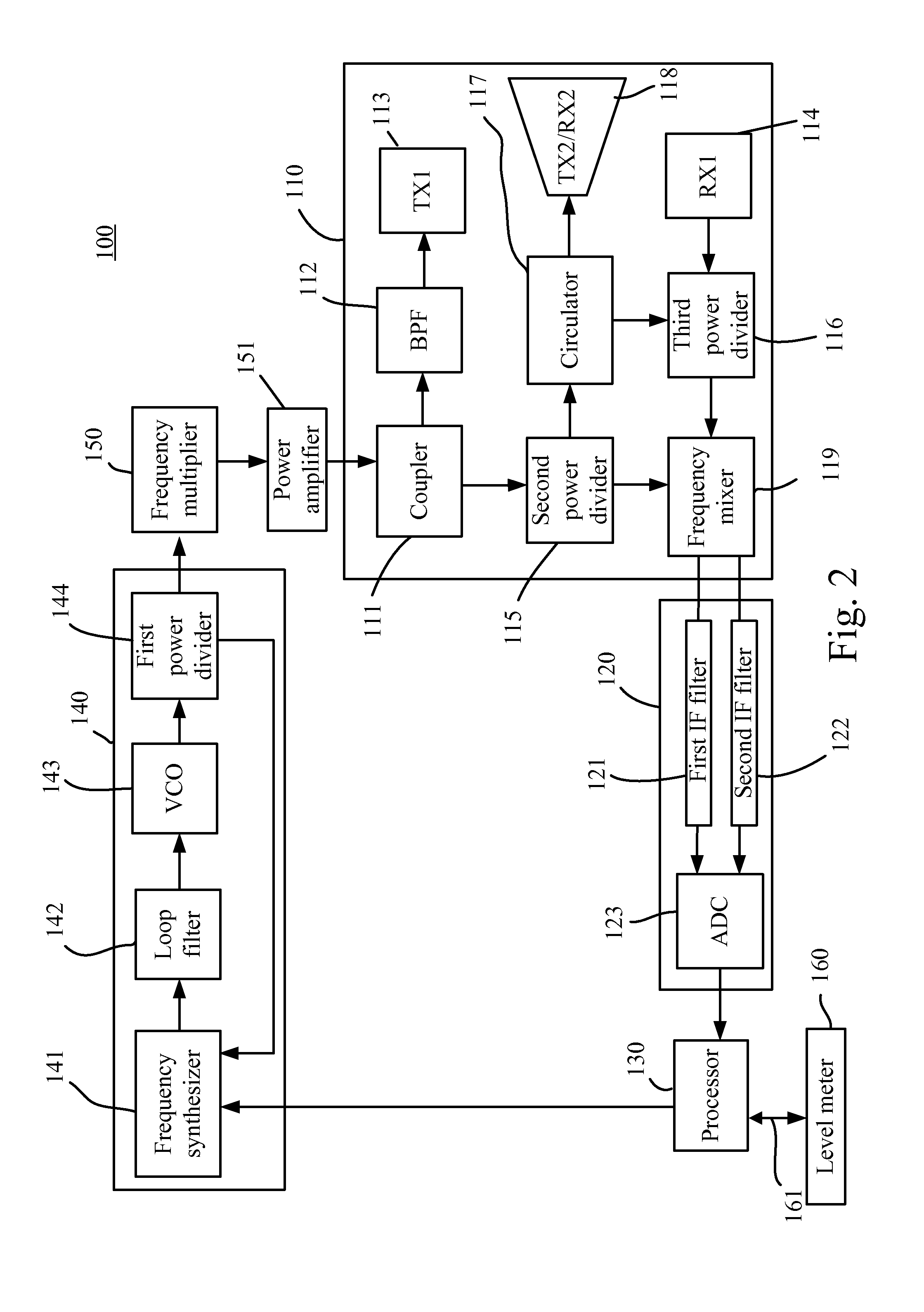
[0023]Please refer to FIG. 2. FIG. 2 is a functional block diagram of the measuring device 100. The measuring device 100 comprises a RF transceiving module 110, an IF module 120, a processor 130, a phase locked loop 140, a frequency multiplier 150, and a power amplifier 151. The RF transceiving module 110 is used for alternatively transmitting a first frequency modulation continuous wave (FMCW) signal and a first continuous wave (CW) signal to the fluid 20 and for receiving a second FMCW signal and a second CW sign...


PUM


Abstract

A device for measuring a surface speed and a liquid level of a fluid is disclosed. The device includes a RF transceiving module for alternatively transmitting a first FMCW signal and a first CW signal to the fluid, and receiving a second FMCW signal and a second CW signal reflected from the fluid. A processor is used for calculating the liquid level of the fluid based on a frequency difference between the first FMCW signal and the second FMCW signal, and for calculating the surface speed of the fluid based on a frequency difference between the first CW signal and the second CW signal. Since the device integrates functions of measuring the surface speed and the liquid level of a fluid, it reduces an occupied room and facilitates a synchronization of data transmission.

Description

BACKGROUND OF THE INVENTION[0001]1. Field of the Invention[0002]The present invention relates to a device for automatic measurement, and more particularly, to a device with integration of a flow meter and a level gauge of the river.[0003]2. Description of the Prior Art[0004]It is common to install a flow meter and a level gauge on bridges to automatically monitor the surface speed and the water level of rivers. The flow meter is used for detecting the surface speed of a fluid such flows of a river or a brook. The amount of the river or brook can be determined in a period of time after the surface speed is detected. It facilitates to determine if any damages may happen in the downstream area or if water in downstream reservoirs may be discharged. The flow meter measures the surface speed of a fluid with microwave or sound wave based on the Doppler Effect. The level gauge calculates the distance between the level gauge itself and the surface based on microwave or sound wave (ultrasoni...

Claims


Application Information

Patent Timeline
Patent Type & Authority Applications(United States)
IPC IPC(8): G01S13/58G01F23/284G01F1/00
CPCG01S13/584G01F23/284G01F1/00G01F1/002G01F1/66G01S7/03G01S7/034G01S7/354G01S13/003G01S13/34G01S13/343G01S13/88
Inventor LIN, HUNG-CHUNCHANG, SHOU-CHENGTSAO, PING-CHANGCHIU, SHANG-FONGCHANG, CHI-HO
Owner U&U ENG
Why Eureka
Try Eureka