Imprint apparatus and article manufacturing method

Active Publication Date: 2017-02-02
CANON KK
View PDF5 Cites 0 Cited by
  • Summary
  • Abstract
  • Description
  • Claims
  • Application Information

AI Technical Summary

Benefits of technology

[0009]The present invention can provide, for example, an imprint apparatus that is advantageous for suppressin

Problems solved by technology

An imprint apparatus using the above technology may cause distortion of the patter

Method used


Image

  • Imprint apparatus and article manufacturing method
  • Imprint apparatus and article manufacturing method
  • Imprint apparatus and article manufacturing method

Examples


Example

First Embodiment

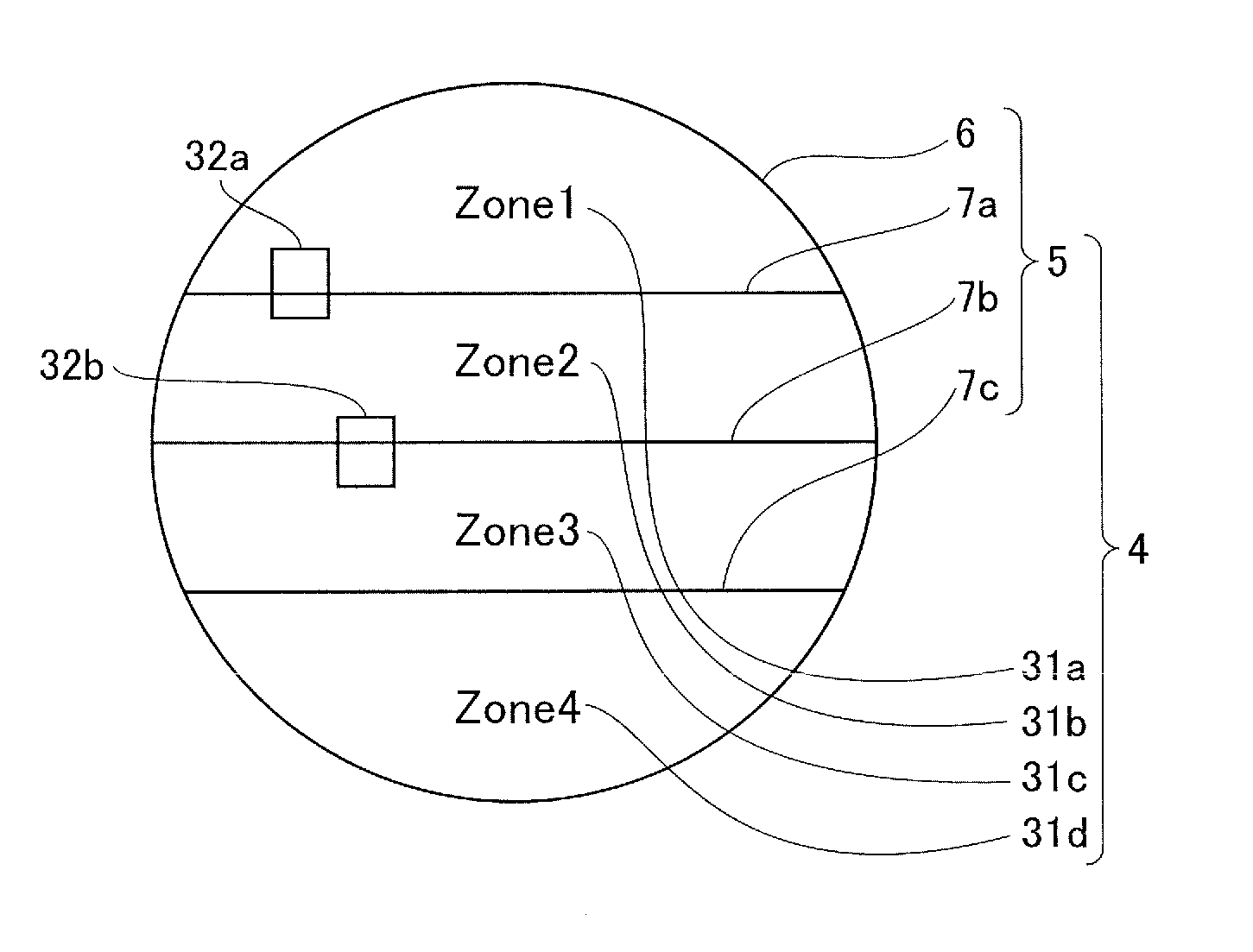
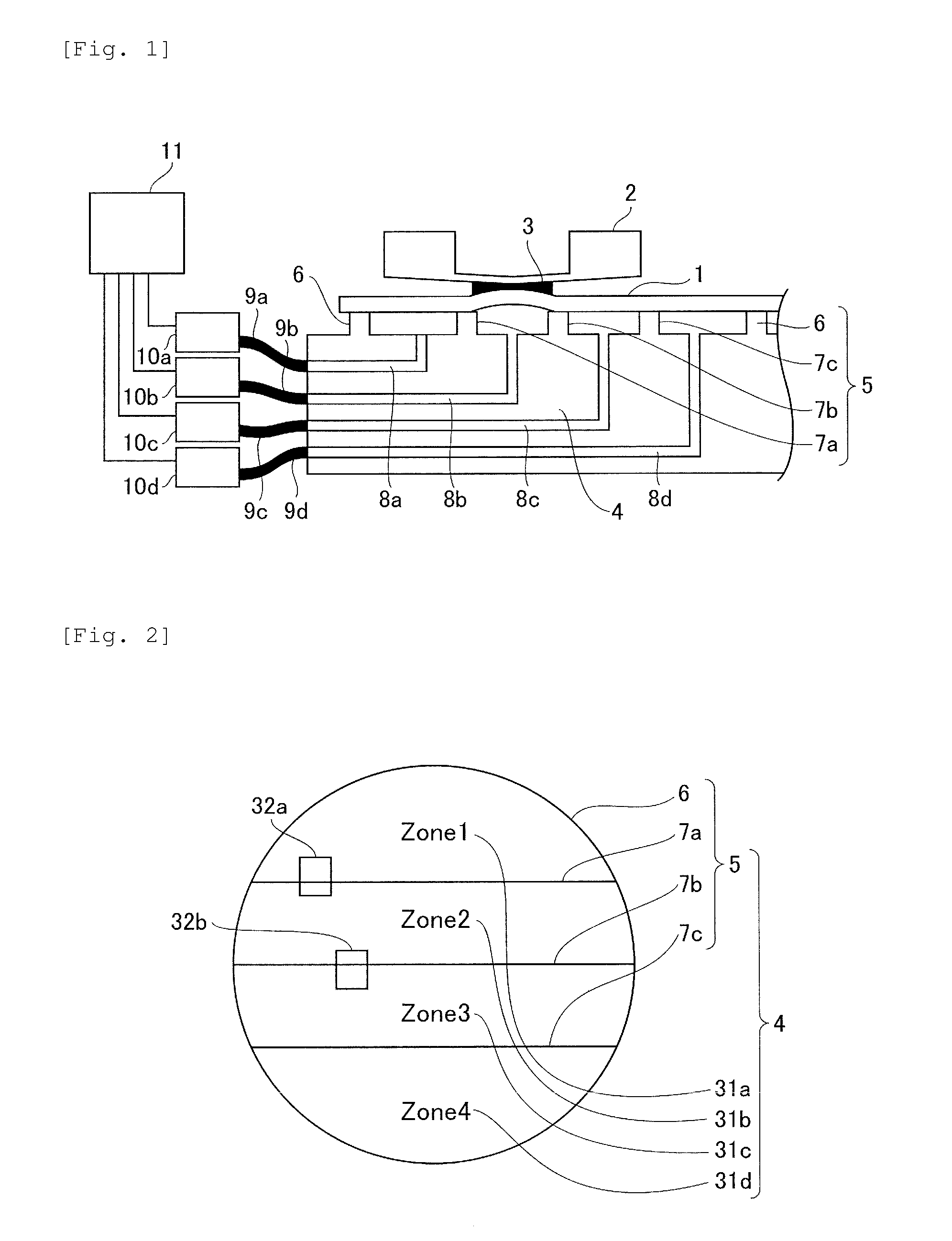
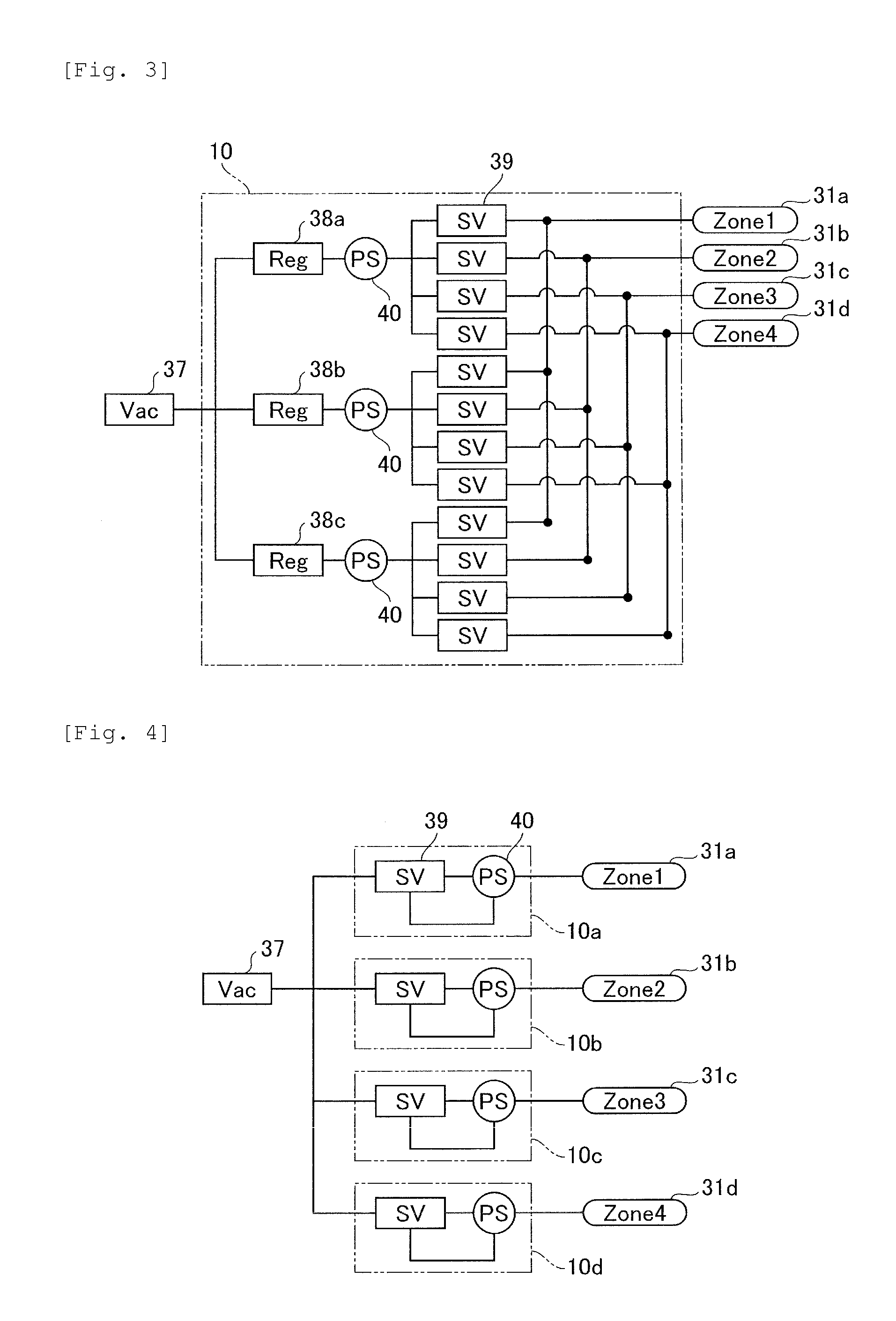
[0020]Firstly, a description will be given of an imprint apparatus enable to apply a substrate holding device according to a first embodiment of the present invention thereto. FIG. 1 is a schematic diagram illustrating a configuration of an imprint apparatus according to the present embodiment. The imprint apparatus is used in manufacture of devices such as semiconductor devices as an article and contacts an uncured resin 3 applied to a substrate (wafer) 1 with a concave and convex pattern formed on a surface of a mold 2 to transfer a reversed image of the pattern on the substrate 1. The imprint apparatus shown in FIG. 1 comprises a substrate holding device (substrate holding unit) 4 for holding (fixing) the substrate 1, a mold 2 arranged opposite to the substrate holding device 4, and a controller 11 for controlling the whole apparatus. The substrate holding device 4 according to the present embodiment is configured to divide a suction area (holding area) for holdin...

Example

Second Embodiment

[0032]Next, a description will be given of an imprint apparatus enable to apply a substrate holding device according to a second embodiment of the present invention thereto. The whole configuration of the imprint apparatus in the present embodiment is similar to that shown in FIG. 1. In this embodiment, a detailed description will be given of another example of the suction area of the substrate holding device 4. FIG. 6 illustrates an exemplary configuration of a suction area of the substrate holding device 4 according to the present embodiment in detailed. As shown in FIG. 6, the substrate holding device according to the present embodiment comprises a suction area 31e (Zone 5) as a periphery holding area that is disposed around each suction area 31a-31d divided into four parts as described in the first embodiment. The above point differs from the configuration of the first embodiment. It is noted that same reference numerals are provided to each of the same componen...


PUM

PropertyMeasurementUnit
Forceaaaaaaaaaa
Pressureaaaaaaaaaa
Widthaaaaaaaaaa

Abstract

Provided is an imprint apparatus for contacting a resin applied to a substrate with a mold to perform patterning on the substrate. The imprint apparatus includes a substrate holding unit for holding the substrate, wherein the substrate holding unit comprises a plurality of holding areas arranged in a predetermined direction, the plurality of holding areas has different width dimension in the direction respectively based on positions in the direction, a surface ratio between two holding areas of the plurality of holding areas with different width dimension respectively is within a range of 0.8 to 1.2.

Description

TECHNICAL FIELD[0001]The present invention relates to an imprint apparatus and an article manufacturing method.BACKGROUND ART[0002]The demand for micronization of semiconductor devices, MEMSs and the like has increased, and in addition to the conventional photolithography technologies, microfabrication technology has attracted attention, in which uncured resin applied on a substrate (wafer) is molded by using a mold and a pattern is formed on the substrate. This technology is referred to as “imprint technology” and a fine structure can be formed on the substrate in several nanometers order. One example of the imprint technology is a photo-curing method. In an imprint apparatus that uses this photo-curing method, firstly, uncured resin (photo-curable resin) is applied in a patterning area on the substrate. Next, the resin on the substrate is contacted with a mold formed a pattern (mold pressing). And then, light is irradiated to cure the resin in a contacted state with the mold. The ...

Claims


Application Information

Patent Timeline
IPC IPC(8): B29C43/58G03F7/00
CPCB29C43/58B29C2043/5866G03F7/0002B29C43/021B29C2043/025B29C2043/3222B29C2043/3652H01L21/027H01L21/6838
Inventor CHOI, BYUNG-JINCHERALA, ANSHUMANYE, ZHENGMAOLU, XIAOMINGLUO, KANGKAWAHARA, NOBUTOMIYAJIMA, YOSHIKAZU
Owner CANON KK
Why Eureka
Try Eureka