
Sensor unit, electronic apparatus and moving object

Active Publication Date: 2015-04-09
SEIKO EPSON CORP
View PDF2 Cites 0 Cited by
  • Summary
  • Abstract
  • Description
  • Claims
  • Application Information

AI Technical Summary

Benefits of technology

The invention is a sensor unit that includes a mount region with no wirings or vias, which prevents distortion and stress and maintains excellent temperature characteristics. The sensor unit is used in electronic devices, motion sensing units, control circuits, and machines. The technical effect of the invention is to provide a linear change in zero point voltage with temperature change and to prevent singular points caused by position shift and direction change of wirings.

Problems solved by technology

Thus, wirings connected to the mount terminals become complicated, and the wirings are generally provided also on an inner periphery where the mount terminals are arranged.
There is a problem that when the bias shift occurs, the zero point voltage significantly varies in the specific temperature region, and excellent temperature characteristics can not be obtained.
Besides, there is a fear that the reliability of measurement results is lowered by the bias shift.

Method used


Image

  • Sensor unit, electronic apparatus and moving object
  • Sensor unit, electronic apparatus and moving object
  • Sensor unit, electronic apparatus and moving object

Examples


modified examples

[0072]Incidentally, no limitation is made to the foregoing embodiment, and various changes and improvements can be made within the scope not departing from the gist. Hereinafter, modified examples will be described.

modified example 1

[0073]FIG. 12 is a perspective view schematically showing an outer appearance of an acceleration sensor 18b mounted on a sensor unit 11 according to a modified example 1 when viewed from the back side. FIG. 13 is a sectional view schematically showing the section of the sensor unit 11 according to the modified example, and is a sectional view schematically showing the section of the sensor unit along line A-A′ shown in FIG. 5.

[0074]In the sensor unit 11 of the modified example 1, as shown in FIG. 12, groove parts 18c are provided in a connection surface 18a on which output terminals 23 of the acceleration sensor 18b are provided. In the sensor unit 11, when distortion occurs in the acceleration sensor 18b, since the groove parts 18c absorb the distortion, the bias shift caused by the distortion can be suppressed.

[0075]Besides, in the sensor unit 11 of the modified example, as shown in FIG. 12 and FIG. 13, a concave-shaped recessed part 18d may be provided in a region exclusive from ...

modified example 2

[0076]FIG. 14 is a plan view schematically showing a plane when a board 17b according to a modified example 2 is viewed in plan from a first surface 17a, and illustration of a sensor is omitted. Besides, FIG. 15 is a sectional view schematically showing a section of a sensor unit 11 including the board 17b along line A-A′ shown in FIG. 14.

[0077]In the board 17b of the modified example 2, as shown in FIG. 14 and FIG. 15, a recessed part 17c as a hole with a bottom is provided exclusively from mount terminals 25 in a mount region 21 set on a first surface 17a of the board 17b. In the board 17b, when distortion due to thermal expansion of the board 17 occurs, the recessed part 17c absorbs the distortion. Thus, the distortion is suppressed from being transmitted to an acceleration sensor 18 mounted on the board 17b, and the bias shift of the acceleration sensor 18 caused by the distortion can be suppressed. Incidentally, the recessed part 17c may be a through hole. When the through hole...


PUM


Abstract

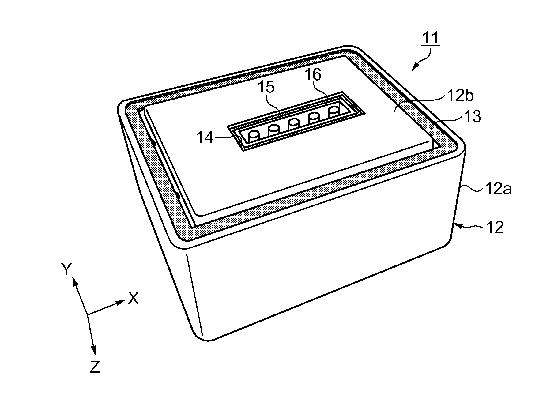
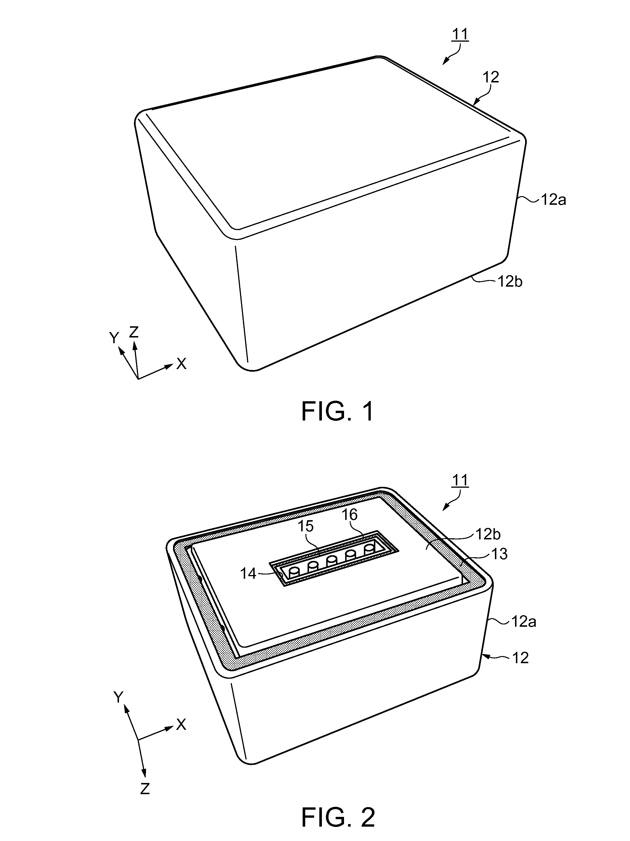
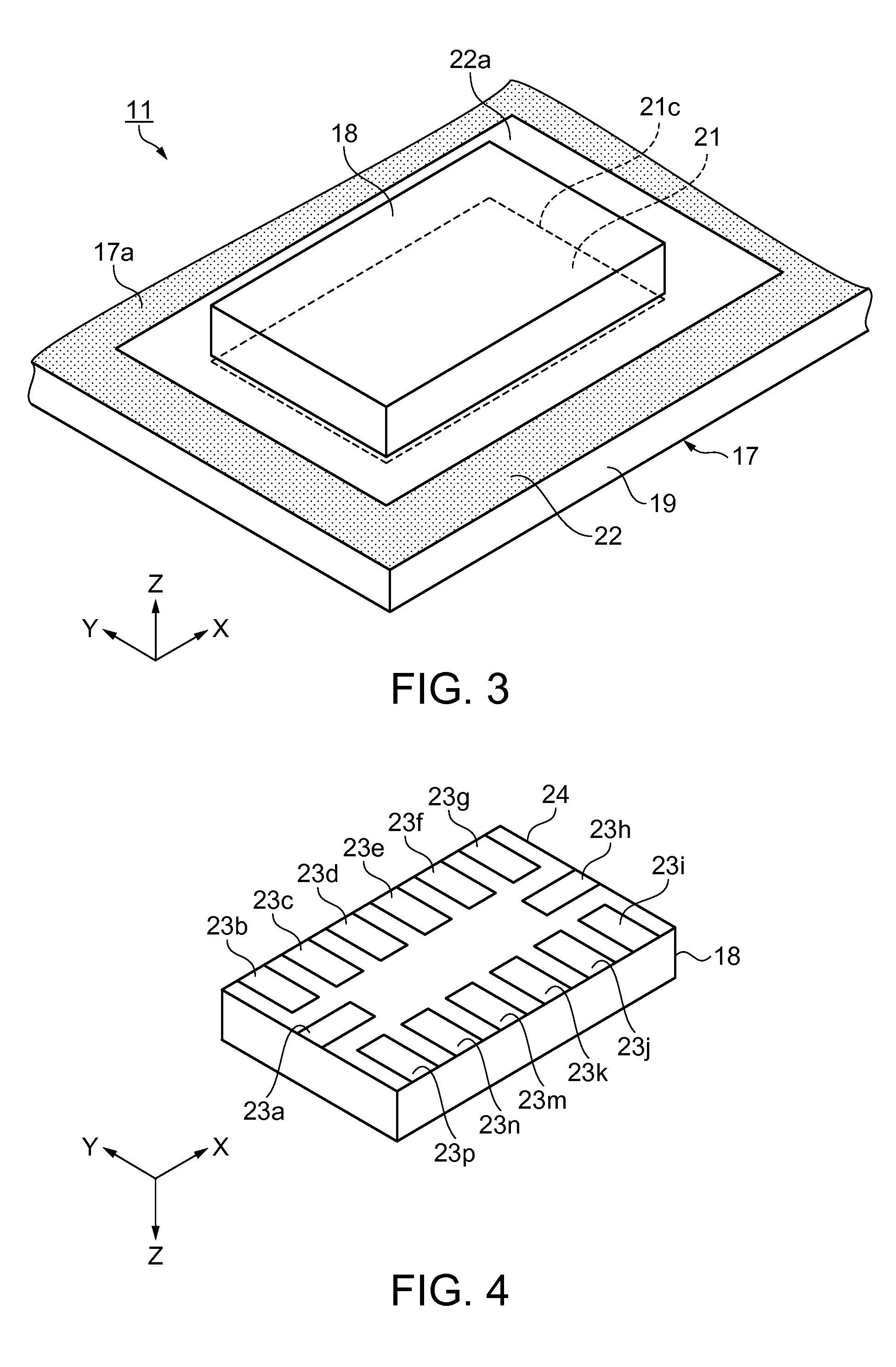
A sensor unit includes a sensor and a mount board on which the sensor is mounted. The mount board includes a mount terminal connected to a terminal provided in the sensor and a wiring extending from the mount terminal. The wiring is not provided in a region where the sensor and the mount board overlap each other when viewed in plan.

Description

BACKGROUND[0001]1. Technical Field[0002]The present invention relates to a sensor unit, an electronic apparatus using the sensor unit and a moving object.[0003]2. Related Art[0004]A physical quantity sensor such as an acceleration sensor or an angular velocity sensor is widely known. The physical quantity sensor is mounted on a mount board by connecting a mount terminal provided on the mount board and a terminal provided on the physical quantity sensor. As the mount terminal, for example, a land grid array can be used. The land grid array includes plural mount terminals arranged in a line along the contour of the physical quantity sensor. The plural mount terminals can be arranged in a line along, for example, one side of the square contour, or form a line so as to go round the contour. In recent years, with miniaturization of an electronic apparatus using a sensor unit, miniaturization of the sensor unit is required, and the mounting density thereof increases. Thus, wirings connect...

Claims


Application Information

Patent Timeline
IPC IPC(8): G01P1/02G01P3/00G01P15/00
CPCG01P1/02G01P3/00G01P15/00G01P1/006G01P1/023
Inventor SAKUMA, MASAYASUCHINO, TAKETO
Owner SEIKO EPSON CORP
Learn More