Objective optical system and optical pickup apparatus

Inactive Publication Date: 2006-12-28
KONICA MINOLTA OPTO
View PDF7 Cites 6 Cited by
  • Summary
  • Abstract
  • Description
  • Claims
  • Application Information

AI Technical Summary

Benefits of technology

[0008] The object of the present invention is to solve the aforementioned problems and to provide an objective optical system for optic

Problems solved by technology

However, the plastic single lens has a problem that spherical aberration caused by changes of refractive index resulting from temperature fluctuations grows greater, though it has the aforesaid advantages.
However, there is sometimes an occasion wherein so-called mode hopping in which the center wavelength skips for several nanometers in a moment in the laser light source used in an optical pickup apparatus, and an apparatus pro

Method used


Image

  • Objective optical system and optical pickup apparatus
  • Objective optical system and optical pickup apparatus
  • Objective optical system and optical pickup apparatus

Examples


Example

Example 1

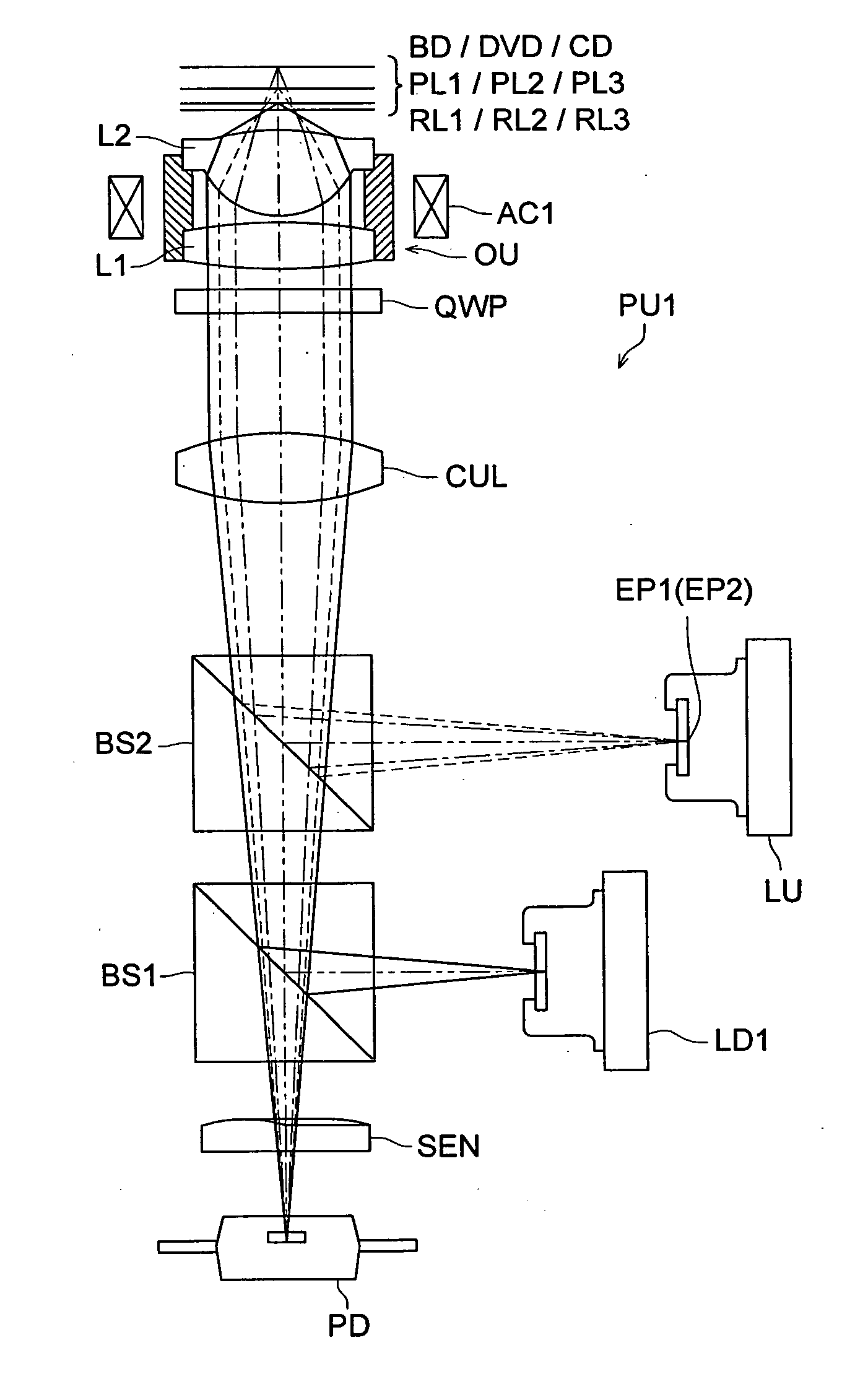
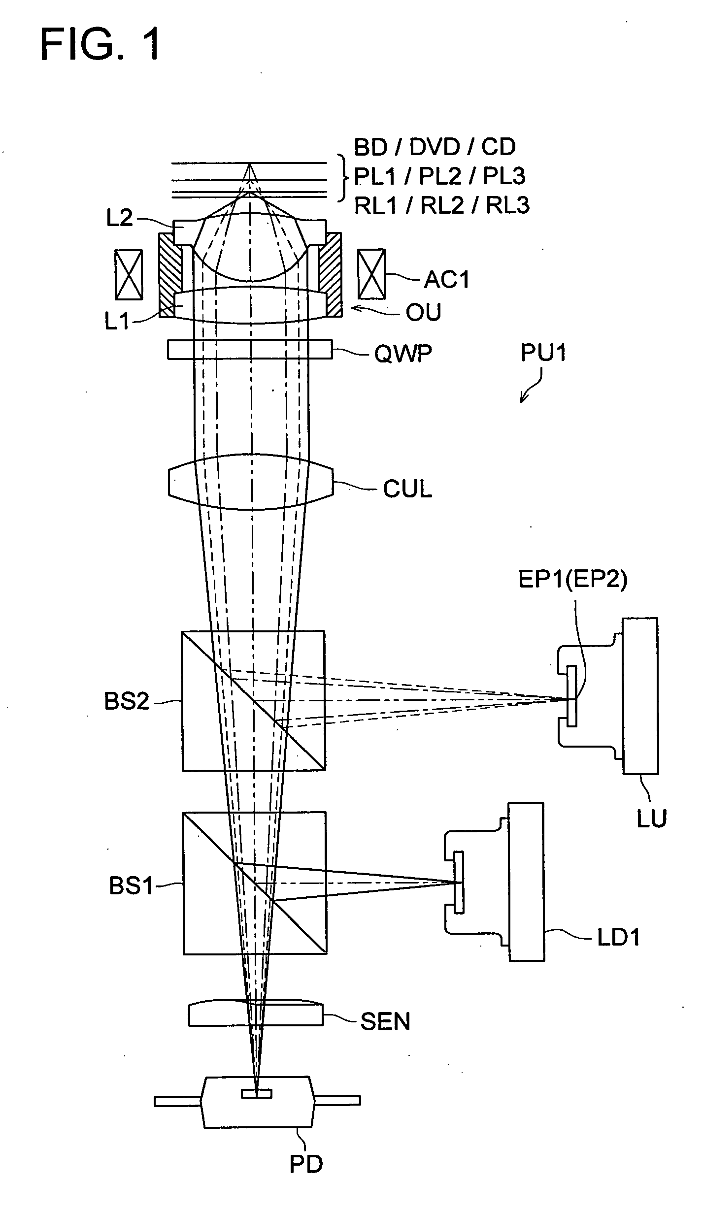
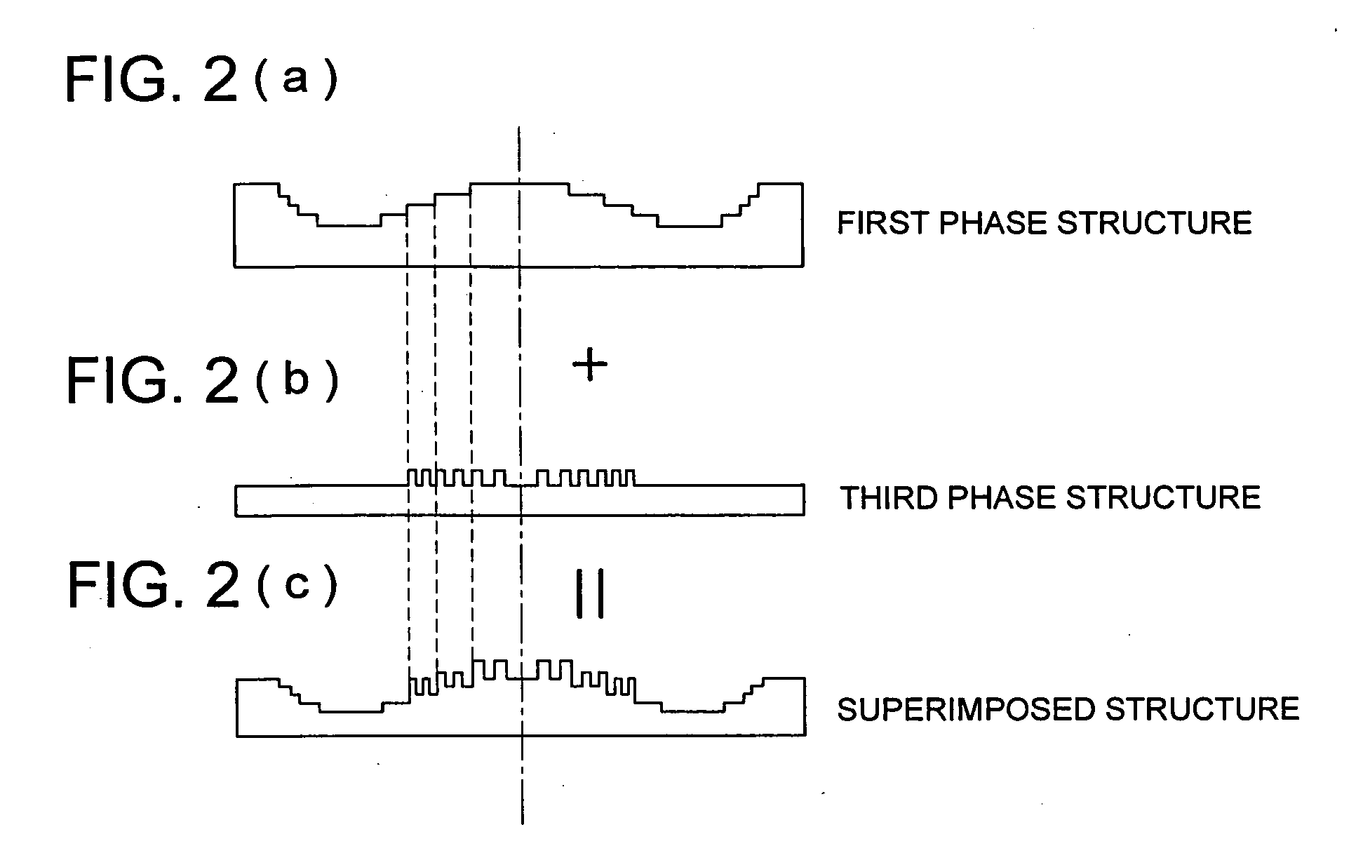
[0116] Table 1 shows lens data of Example 1 (including a design wavelength, a focal length, a numerical aperture on the image side and a magnification). FIG. 3 is a cross sectional view of the objective optical system in Example 1. In this case, first lens L1 has optical surface S1 on the light source side and optical surface S2 on the optical disc side. Second lens L2 has optical surface S3 on the light source side and optical surface S4 on the optical disc side. In Example 1, the optical surface S1 on the light source side of the first lens is flat, and the optical surface S2 on the side of the optical disk is convex and aspherical. The optical surface S1 is provided with the first and third phase structures. The optical surface S2 is provided with the second phase structure. In the column of the first phase structure in the Table 1, i represents the number of ring-shaped zone, hi-1 represents a height in the direction perpendicular to the optical axis of a point where t...

Example

Example 2

[0119] Table 2 shows lens data of Example 2 (including a design wavelength, a focal length, a numerical aperture on the image side and a magnification). A section of the objective optical system of Example 2 is shown in FIG. 4. In Example 2, first lens L1 has optical surface S1 on the light source side and optical surface S2 on the optical disc side. Second lens L2 has optical surface S3 on the light source side and optical surface S4 on the optical disc side. In Example 2, each of both optical surfaces S1 and S2 of the first lens is a convex aspheric surface. The first phase structure and the third phase structure are provided on the optical surface S1, and the second phase structure is provided on the optical surface S2. Incidentally, in the Example 2, there is described only an optical path difference given by each ring-shaped zone, and step differences to give this optical path difference are assumed to be provided on optical surface S1 of the first lens on the light s...


PUM


Abstract

An objective optical system according to the present invention is provided for use in an optical pickup apparatus for recording or reproducing information on an information recording surface of a first optical information recording medium using a first light flux emitted from a first light source. The objective optical system is provided with: a first lens with a positive refractive power including plastic; a second lens with a positive refractive power including plastic; and a first phase structure. A wavefront aberration change amount of the objective optical system when a wavelength of the first light flux changes, and a wavefront aberration change amount of the objective optical system when an ambient temperature of the objective optical system satisfy the predefined condition.

Description

[0001] This application is based on Japanese Patent Application No. 2005-179677 filed on Jun. 20, 2005, in Japanese Patent Office, the entire content of which is hereby incorporated by reference. FIELD OF THE INVENTION [0002] The present invention relates to an objective optical system for use in an optical pickup apparatus and to the optical pickup apparatus, and in particular, to an objective optical system comprising a plurality of plastic lenses utilized in an optical pickup apparatus and the optical pickup apparatus employing the objective optical system. BACKGROUND OF THE INVENTION [0003] In recent years, research and development are advanced rapidly for a high density optical disc system that employs a violet semiconductor laser having a wavelength of about 400 nm, and is capable of conducting recording / reproducing of information. As an example, information of 23-27 GB per one layer can be recorded on an optical disc having a diameter of 12 cm that is the same size as in DVD ...

Claims


Application Information

Patent Timeline
IPC IPC(8): G11B7/135G11B7/00G11B7/125
CPCG02B27/0037G02B27/4238G02B27/4294G11B2007/13727G11B7/1367G11B7/1374G11B2007/0006G11B7/1275
Inventor NOGUCHI, KAZUTAKAATARASHI, YUICHI
Owner KONICA MINOLTA OPTO
Why Eureka
Try Eureka