Motor provided with deceleration mechanism

Active Publication Date: 2020-06-25
MITSUBA CORP
View PDF0 Cites 1 Cited by
  • Summary
  • Abstract
  • Description
  • Claims
  • Application Information

AI Technical Summary

Benefits of technology

[0017]According to the present invention, on one side of the worm wheel in the axial direction, one-side thinned portions recessed toward the other side of the worm wheel in the axial direction are arranged. Further, on the one side of the worm wheel in the axial direction, reinforcing portions reinforcing areas between the one-side thinned portions and to

Problems solved by technology

On the other hand, as for the worm wheel made of resin, defects such a

Method used


Image

  • Motor provided with deceleration mechanism
  • Motor provided with deceleration mechanism
  • Motor provided with deceleration mechanism

Examples


first embodiment

[0027]Hereinafter, the present invention will be described in detail with reference to drawings.

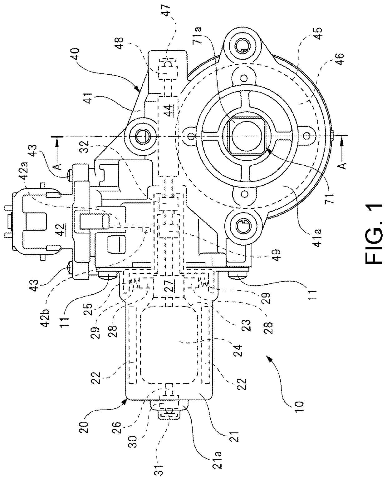
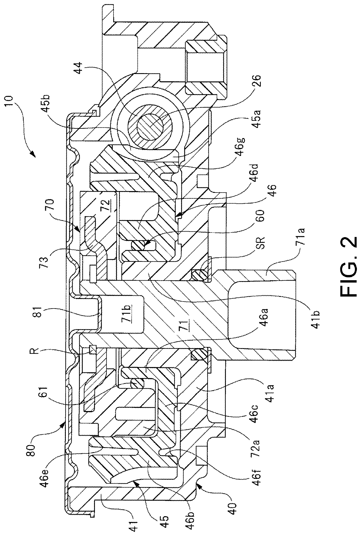
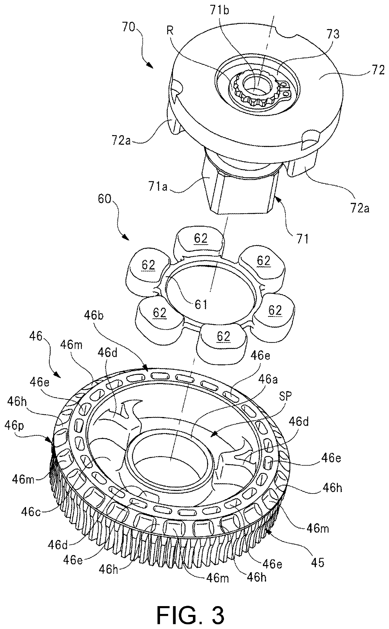
[0028]FIG. 1 illustrates a partial cross-sectional view illustrating a motor provided with deceleration mechanism according to the present invention. FIG. 2 illustrates a cross-sectional view taken along A-A line of FIG. 1. FIG. 3 illustrates an exploded perspective view illustrating a worm wheel, a damper member, and an output member. FIGS. 4(a) and (b) illustrate plan views illustrating detailed structures of a front side and a back side of the worm wheel. FIG. 5 illustrates a cross-sectional view taken along B-B line of FIG. 4(a). FIG. 6 illustrates an enlarged view of a broken-line circle C portion of FIG. 4(a). FIG. 7 illustrates a partially enlarged view of the worm wheel as viewed from a lateral side.

[0029]The motor provided with deceleration mechanism 10 illustrated in FIG. 1 is used as a driving source of a power window device installed in a vehicle such as an automobile to drive...

second embodiment

[0084]FIG. 8 illustrates a cross-sectional view of a worm wheel of the second embodiment and corresponds to FIG. 5.

[0085]As illustrated in FIG. 8, a worm wheel 90 of the second embodiment is different from the worm wheel 46 of the first embodiment (see FIG. 5) in that a plurality of first thinned portions (one-side thinned portions) 46e and a plurality of second thinned portions (other-side thinned portions) 46f are alternately arranged on one side and the other side of the worm wheel 90 in an axial direction so as to alternately appear in a circumferential direction of the large-diameter cylindrical portion 46b (worm wheel 90).

[0086]Specifically, an interval between a line segment L2 passing through a central portion of the first thinned portions 46e and extending in the axial direction of the worm wheel 90 and a line segment L3 passing through a central portion of the second thinned portions 46f and extending in the axial direction of the worm wheel 90 corresponds to an interval o...


PUM


Abstract

On one side of a worm wheel (46) in an axial direction, first thinned portions (46e) recessed toward the other side of the worm wheel (46) in the axial direction are arranged. Further, on the one side of the worm wheel (46) in the axial direction, reinforcing portions (46h) reinforcing areas between the first thinned portions (46e) and tooth portions (45) of the worm wheel (46) are arranged. Therefore, it is possible to reduce a weight of the worm wheel (46) and to suppress occurrence of distortion of the tooth portions (45) by the first thinned portions (46e). In addition, it is possible to sufficiently increase the strength of the worm wheel (46) in the vicinity of the tooth portions (45) by the reinforcing portions (46h).

Description

BACKGROUND OF THE INVENTIONTechnical Field[0001]The present invention relates to a motor provided with deceleration mechanism which decelerates and outputs rotation of an armature shaft.Related Art[0002]Conventionally, a motor provided with deceleration mechanism which is small in size and obtains a large output has been used as a driving source of a power window device, a sunroof device, etc. installed in a vehicle such as an automobile. The motor provided with deceleration mechanism is driven by an operation of an operation switch and the like in an interior of the vehicle, thereby opening / closing the window glass, the sunroof, etc.[0003]For example, a technology described in patent literature 1 has been known as the motor provided with deceleration mechanism used for the driving source of the power window device, the sunroof device, etc. The motor provided with deceleration mechanism described in patent literature 1 includes a motor unit and a gear unit. The motor unit is provide...

Claims


Application Information

Patent Timeline
IPC IPC(8): H02K7/116H02K5/14
CPCH02K5/148H02K7/1166H02K11/215F16H55/22F16H2057/0213E05Y2900/55F16H2057/02034F16H1/16H02K2213/03H02K7/10F16H2057/02082
Inventor UCHIMURA, HIROYUKIKUMAKURA, RYOOGINO, NARUHITONISHI, TAKESHI
Owner MITSUBA CORP
Why Eureka
Try Eureka