
Pneumatic tire

a technology of pneumatic tires and bead portions, which is applied in the direction of heavy-duty vehicles, vehicle components, vehicles, etc., can solve the problems of reducing the resistance to wear, promoting an increased tendency of tire deformation in the tire-width direction, and increasing the distortion of the bead portion, so as to achieve enhanced bead durability

Inactive Publication Date: 2017-02-02
TOYO TIRE & RUBBER CO LTD
View PDF4 Cites 0 Cited by
  • Summary
  • Abstract
  • Description
  • Claims
  • Application Information

AI Technical Summary

Benefits of technology

The patent relates to improving the durability of the bead portion of a tire by preventing distortion while ensuring that the tire does not grow in size. It does this by introducing a reinforcement belt with a small angle (between 0 to 5 degrees) to hold the tire's shape and reduce distortion at the edges. However, this can lead to increased deformation in the tire's radial direction, which negatively impacts bead durability. The patent aims to address this issue and enhance bead durability while ensuring that the tire does not grow larger in size.

Problems solved by technology

However, the small cord angle of the reinforcement belt ranging from approximately 0 to 5 degrees causes an excessively large binding force in a tire-radial direction, thereby promoting an increased tendency in the deformation of a tire in the tire-width direction.
As a result, distortion in the bead portion is increased, causing lower resistance against a defect such as separation in the bead portion (bead durability).

Method used


Image

  • Pneumatic tire
  • Pneumatic tire
  • Pneumatic tire

Examples


examples

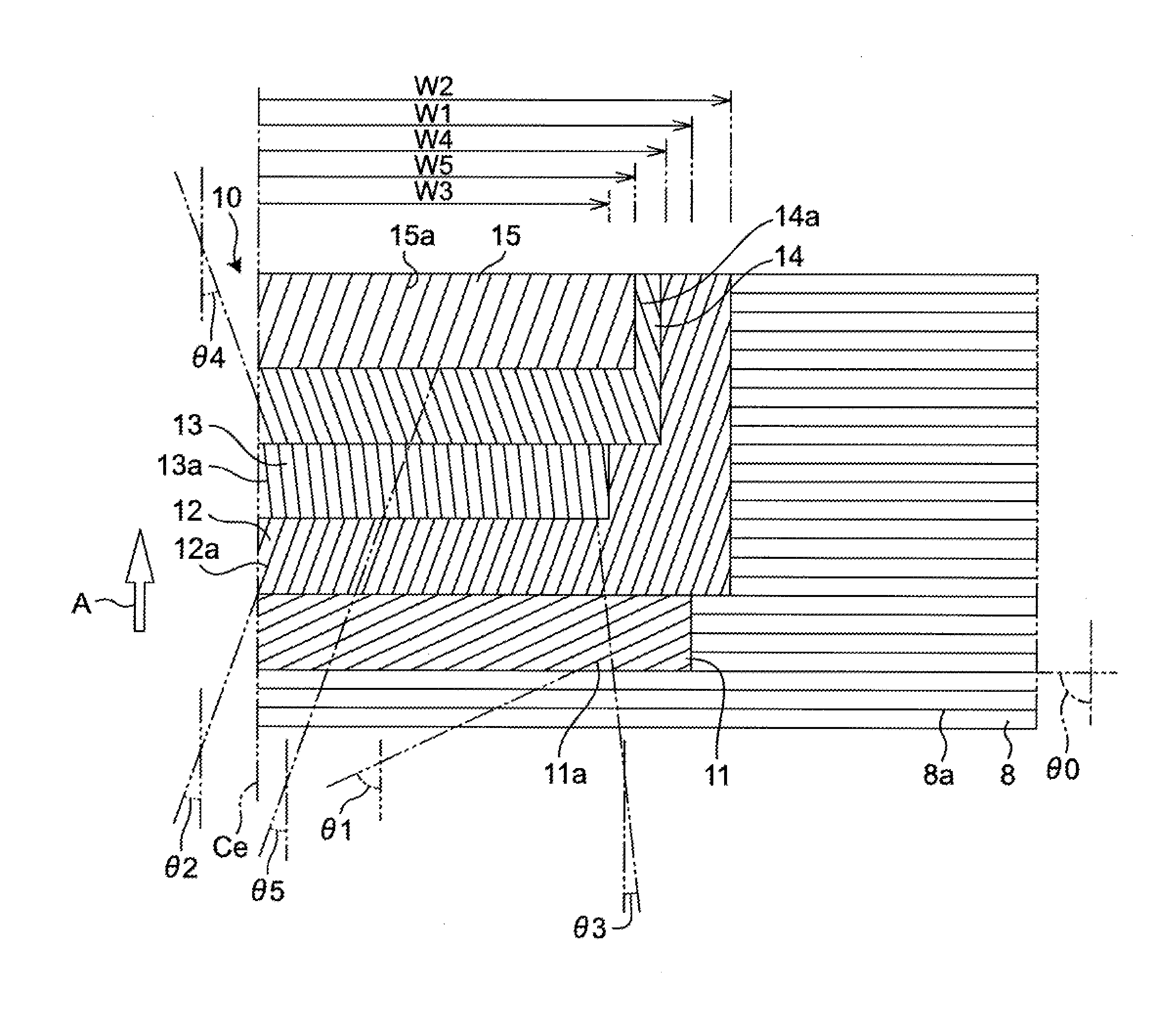
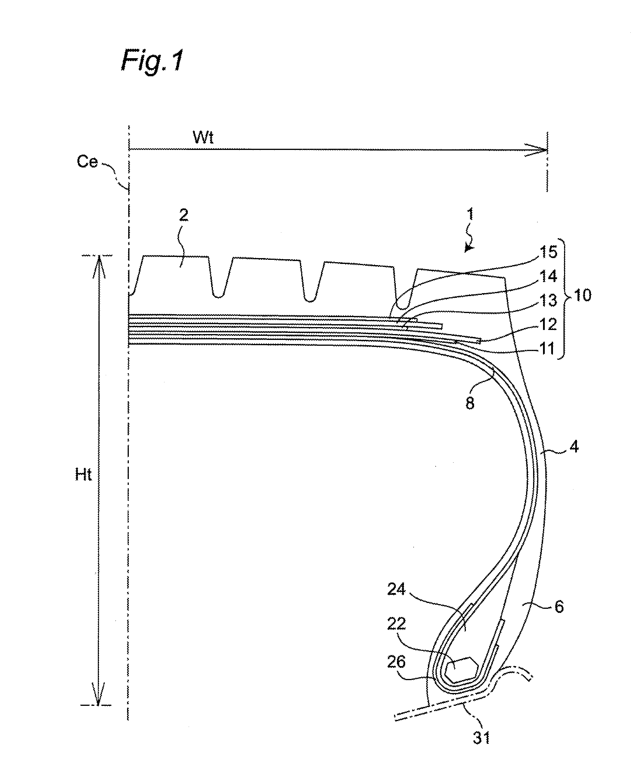
[0055]Tires according to Comparative Examples 1 to 5 and tires according to Examples 1 to 4 shown in the following Table 3 were subjected to an evaluation test performed for evaluating belt durability and bead durability. Assume that data which are not described particularly hereinafter are shared in common by the tires according to Comparative Examples 1 to 5 and the tires according to Examples 1 to 4. Particularly, in all of Comparative Examples 1 to 5 and the tires according to Examples 1 to 4, a tire size is set to 445 / 50R22.5.

TABLE 3ComparativeComparativeComparativeComparativeComparativeExample 1Example 2Example 3Example 4Example 5NoteNoReinforcementCord angleCord angle Width W3reinforcementbelt extending in θ3θ3excessivelybeltcircumferentialexcessivelyexcessivelysmall(FIG. 5)directionsmalllargeCord angle θ3—05107(degrees) ofreinforcementbeltWidth W3 of—290290290180reinforcementbelt(mm)W3 / Wt*100(%)—66666641Belt durability10013012710590Bead durability10090100120100Example 1Examp...


PUM


Abstract

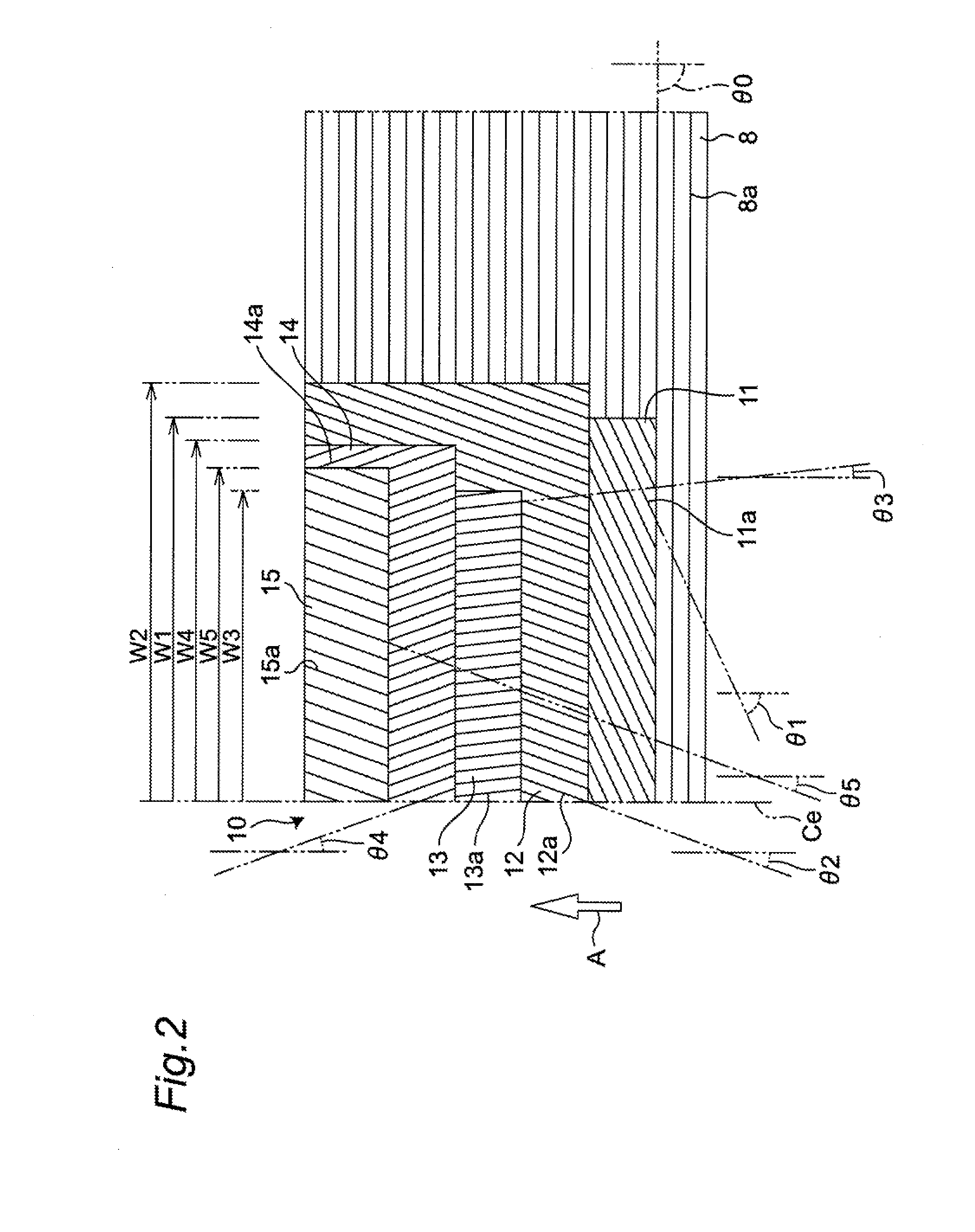
A pneumatic tire has a belt layer arranged between a carcass and a tread portion. The belt layer has a first main working belt, a second main working belt arranged at an outer side of the first main working belt in a tire-radial direction, and a reinforcement belt. A cord angle of the second main working belt differs from a cord angle of the first main working belt in a direction with respect to a tire-circumferential direction. A cord angle of the reinforcement belt is not smaller than 6 degrees and not larger than 9 degrees. A width of the reinforcement belt is equal to or wider than 50% of a tire-section width and not wider than either narrower one of the first and second main working belts.

Description

CROSS-REFERENCE TO RELATED APPLICATIONS[0001]This application claims priority of Japanese Patent Application No. 2015-150096 filed on Jul. 29, 2015, the content of which is incorporated herein by reference.BACKGROUND OF THE INVENTION[0002]Technical Field[0003]The present invention relates to a pneumatic tire.[0004]Related Art[0005]In a pneumatic radial tire for a heavy load used for a vehicle such as a truck or a bus, it has been known that a belt layer arranged between a carcass and a tread portion includes a reinforcement belt with cords having a small inclination angle with respect to the tire-circumferential direction (cord angle) of 0 to 5 degrees (see JP 2007-45334 A, JP 2005-104437 A, JP 2014-189243 A, Japanese Patent No. 5182455, for example). The reinforcement belt is intended to suppress a growth of the tire in the radial direction.SUMMARY[0006]The small cord angle of the reinforcement belt ranging from approximately 0 to 5 degrees increases a force for holding a shape of ...

Claims


Application Information

Patent Timeline
Patent Type & Authority Applications(United States)
IPC IPC(8): B60C9/20
CPCB60C9/20B60C2200/06B60C2009/2061B60C2009/2016B60C9/18B60C2009/2012B60C9/2006B60C9/28
Inventor NISHIDA, YUYA
Owner TOYO TIRE & RUBBER CO LTD
Learn More