
Passenger protecting device for vehicle

a technology for protecting devices and passengers, which is applied in the direction of vehicle components, pedestrian/occupant safety arrangements, vehicle arrangements, etc., can solve the problems of delayed difficulty in circulating gas generated by inflators, and delay in completion of inflation of seat cushion airbag portions, etc., to achieve simple structure, reduce costs, and suppress interference with other airbags

Active Publication Date: 2017-02-02
TOYOTA JIDOSHA KK
View PDF2 Cites 23 Cited by
  • Summary
  • Abstract
  • Description
  • Claims
  • Application Information

AI Technical Summary

Benefits of technology

The present invention provides a passenger protecting device for a vehicle that can prevent the passenger from moving towards the front of the seat in the event of a side collision. The device effectively protects the femoral region, which is the thigh bone, from injury. The device offers wide coverage from the femoral region to the lumbar region, but it also helps to avoid interference with other airbags.

Problems solved by technology

However, in the techniques disclosed in the above-described patent documents, the side airbag and the seat cushion airbag inflate simultaneously.
Further, by causing the side airbag portion to inflate prioritarily (earlier), completion of inflation of the seat cushion airbag portion can be delayed even in a structure in which the side airbag portion and the seat cushion airbag portion are in communication with each other.
Due thereto, it is difficult for the gas generated from the inflator to flow to the seat cushion airbag portion.
Namely, gas from the inflator flows prioritarily to the side airbag portion, and completion of inflation of the seat cushion airbag portion can be delayed.
Namely, completion of inflation of the seat cushion airbag portion can be delayed.
Due thereto, gas can be made to flow prioritarily to the side airbag portion, and completion of inflation of the seat cushion airbag portion can be delayed.
Further, because this inflation limiting member is not broken until a predetermined inflation pressure is reached, completion of inflation of the seat cushion airbag portion can be delayed.

Method used


Image

  • Passenger protecting device for vehicle
  • Passenger protecting device for vehicle
  • Passenger protecting device for vehicle

Examples


first embodiment

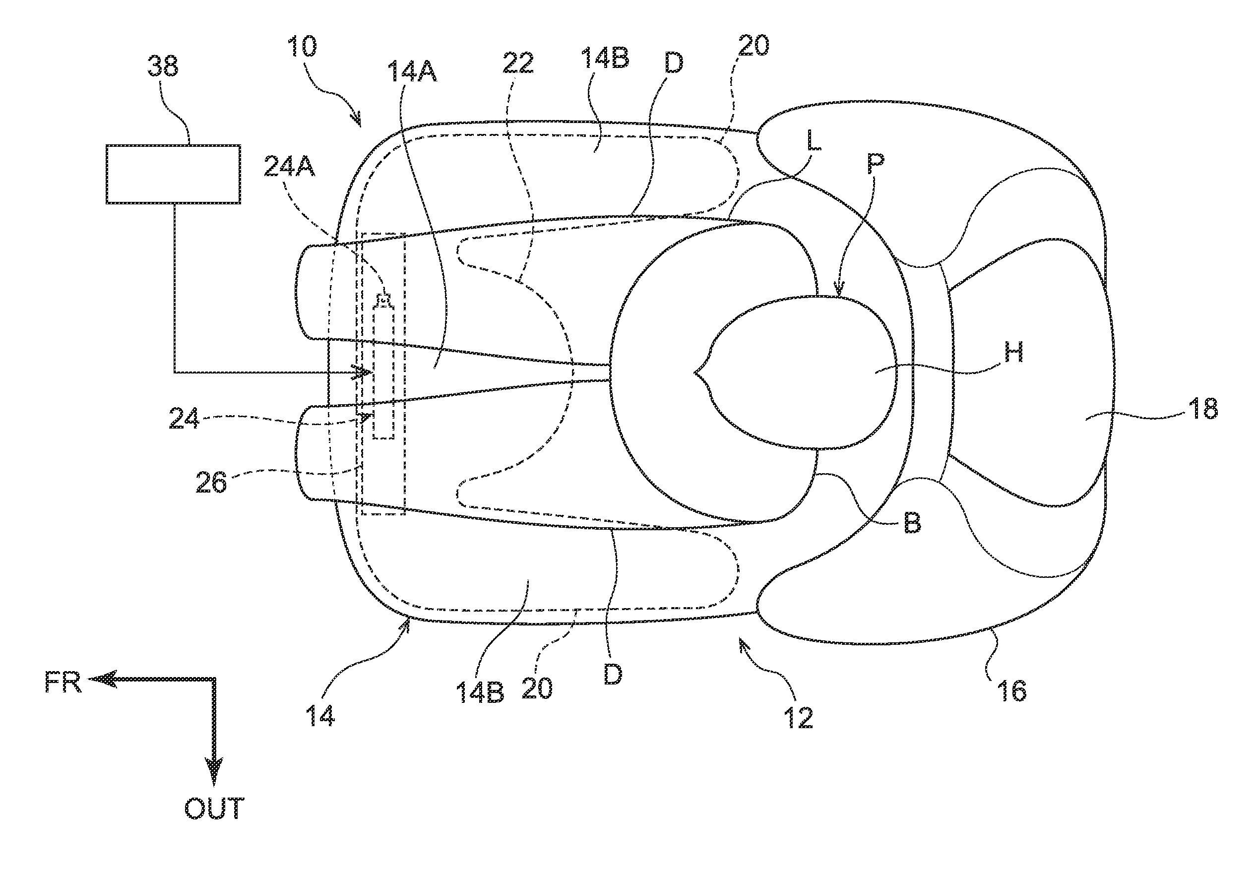
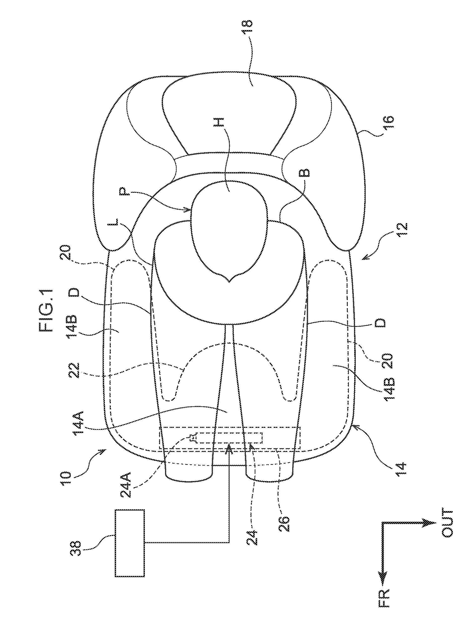
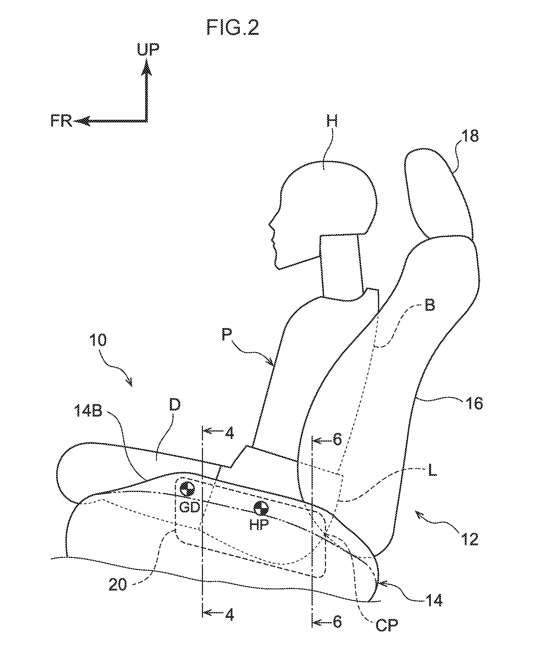
[0048]A passenger protecting device 10 for a vehicle relating to a first embodiment of the present invention is described on the basis of FIG. 1 through FIG. 6. Note that arrow FR and arrow UP that are shown appropriately in the respective drawings indicate the forward direction (the direction in which a seated person faces) and the upward direction of a vehicle seat 12, respectively. Further, when description is given by using merely longitudinal, vertical and left-right directions, they mean the longitudinal of the seat longitudinal direction, the vertical of the seat vertical direction, and left and right when facing forward in the seat longitudinal direction, unless stated otherwise. Moreover, arrow OUT that is shown appropriately in the respective drawings means the vehicle transverse direction outer side at an automobile that serves as a vehicle in which the vehicle seat 12 is installed.

[0049](Structure of Passenger Protecting Device for Vehicle)

[0050]As shown in FIG. 1, the p...

second embodiment

[0086]A passenger protecting device 40 for a vehicle relating to a second embodiment is described next on the basis of FIGS. 7A and 7B. Note that structures that are similar to those of the first embodiment are denoted by the same reference numerals, and description thereof is omitted as appropriate. Further, because the vehicle seat is structured similarly to the first embodiment, illustration and description thereof are omitted here.

[0087]As shown in FIGS. 7A and 7B, at the passenger protecting device 40 for a vehicle of the present embodiment (hereinafter simply called “passenger protecting device 40”), a side airbag portion 42 and a seat cushion airbag portion 44 are structured by separate base cloths.

[0088]Concretely, the side airbag portion 42 is structured to include a pair of left and right side portions 42A that extend in the seat longitudinal direction, and a connecting portion 42B that extends in the seat transverse direction and connects the front end portions of the sid...

third embodiment

[0097]A passenger protecting device 50 for a vehicle relating to a third embodiment is described next on the basis of FIGS. 8A and 8B. Note that structures that are similar to those of the first embodiment are denoted by the same reference numerals, and description thereof is omitted as appropriate. Further, because the vehicle seat is structured similarly to the first embodiment, illustration and description thereof are omitted here.

[0098]As shown in FIGS. 8A and 8B, the passenger protecting device 50 for a vehicle of the present embodiment (hereinafter simply called “passenger protecting device 50”) is structured to include the pair of side airbag portions 20, the seat cushion airbag portion 22, the inflator 24 and the diffuser 26.

[0099]Here, the side airbag portions 20 are not folded, whereas the seat cushion airbag portion 22 is folded in the form of a roll in the non-inflated state. Concretely, the seat rear side portion of the seat cushion airbag portion 22 is made into a roll...


PUM


Abstract

A passenger protecting device 10 for a vehicle has: a side airbag portion 20 that is accommodated at an interior of a side support portion 14B, and that, by receiving a supply of gas and inflating at a time of an oblique side collision of a vehicle, causes the side support portion 14B to bulge-out toward the seat upper side; and a seat cushion airbag portion 22 that is accommodated at an interior of the seat portion 14A, and that, by receiving a supply of gas and inflating at a time of an oblique side collision of the vehicle, causes the seat portion 14A to bulge-out toward the seat upper side and raises the femoral region D of the passenger P, and whose inflation is completed later than the side airbag portion 20.

Description

CROSS-REFERENCE TO RELATED APPLICATION[0001]This application claims priority under 35 USC 119 from Japanese Patent Application No. 2015-150925 filed Jul. 30, 2015, the disclosure of which is incorporated by reference herein.BACKGROUND[0002]Technical Field[0003]The present invention relates to a passenger protecting device for a vehicle.[0004]Related Art[0005]Japanese Patent Application Laid-Open (JP-A) No. 2002-145003 discloses an airbag device in which a bag portion for a seat, that by inflating raises the front portion side of a seat portion of a seat cushion, and a bag portion for a side, that by inflating protrudes-out toward the seat upper side from the seat transverse direction outer side of the seat portion and covers the seat transverse direction outer side of a passenger, are inflated simultaneously. JP-A No. 2015-048054 discloses an airbag that includes a main chamber, that is accommodated within the seat surface portion of a seat cushion and that is sectioned into left an...

Claims


Application Information

Patent Timeline
Patent Type & Authority Applications(United States)
IPC IPC(8): B60R21/231B60N2/427B60R21/16B60R21/207B60N2/42
CPCB60R21/231B60R21/207B60R2021/23146B60R21/16B60N2/42763B60N2/42B60R21/23138B60R2021/0055B60N2/914B60R21/233B60R2021/23324B60R21/2338B60R2021/23382
Inventor KOBAYASHI, IPPEIOHNO, MITSUYOSHINAKASHIMA, ATSUSHI
Owner TOYOTA JIDOSHA KK
Learn More