Electric vehicle

a technology of electric vehicles and electric motors, applied in the direction of electric devices, propulsion by batteries/cells, brake systems, etc., can solve the problems of hindering the driver's acceleration and deceleration demand, occupants in the vehicle feel uneasy,

Inactive Publication Date: 2017-02-02
TOYOTA JIDOSHA KK
View PDF0 Cites 7 Cited by
  • Summary
  • Abstract
  • Description
  • Claims
  • Application Information

AI Technical Summary

Benefits of technology

[0040]It is to be noted from FIG. 10 that since the effect resulting from force Fuv being generated by the virtual force generation device 110 cannot be expected in a range where frequency is below fc1, the virtual force generation device 110 may not generate force Fuv. It is also to be noted that if the virtual...

Problems solved by technology

As longitudinal vibration of a wheel is transmitted to a vehicle body via a suspension and the like, occupants in a vehicle feel uneasy due to so called shaky vibration.
As a result, in a situation where a vehicle accelerates and decele...

Method used


Image

  • Electric vehicle
  • Electric vehicle
  • Electric vehicle

Examples


first embodiment

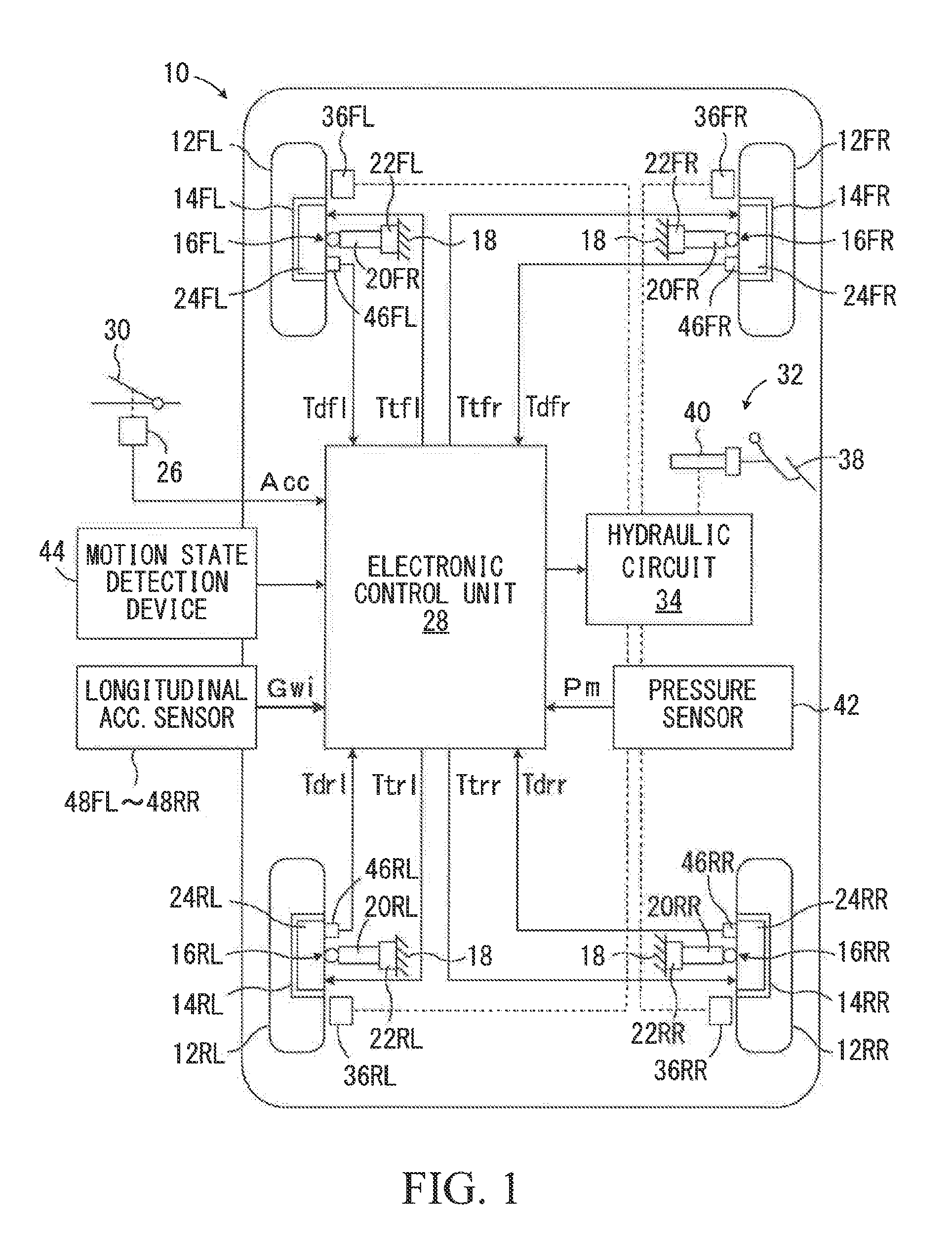
[0053]FIG. 1 is a schematic view for illustrating an electric vehicle 10 according to a first embodiment of the present disclosure applied to a four-wheel drive vehicle of in-wheel motor type. The electric vehicle 10 has left and right front wheels 12FL and 12FR which are steered wheels and left and right rear wheels 12RL and 12RR which are non-steered wheels. The front wheels 12FL and 12FR are supported by wheel support members 14FL and 14FR, respectively, so as to rotate about rotation axes of the wheels. In a similar manner, the rear wheels 12RL and 12RR are supported by wheel support members 14RL and 14RR, respectively, so as to rotate about rotation axes of the wheels. The front wheels 12FL and 12FR are suspended from a vehicle body 18 by front wheel suspensions 16FL and 16FR and the rear wheels 12RL and 12RR are suspended from the vehicle body 18 by rear wheel suspensions 16RL and 16RR.

[0054]The front wheel suspensions 16FL and 16FR include suspension aims 20FL and 20FR, respe...

second embodiment

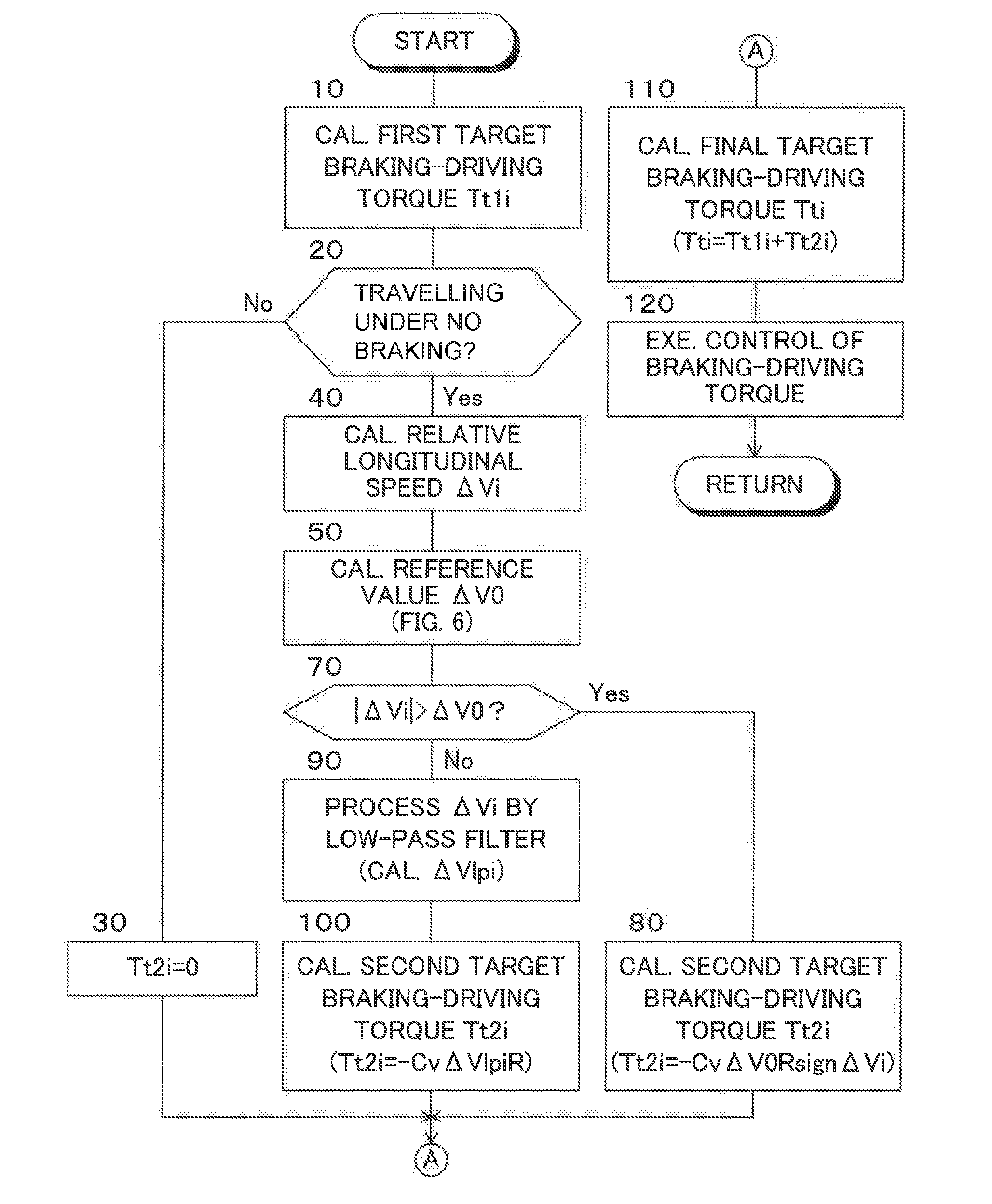
[0085]FIG. 3 is a flowchart for illustrating a routine for controlling braking-driving forces of wheels in an electric vehicle 10 according to the second embodiment which is applied to a four-wheel drive vehicle of in-wheel motor type. Note that, in FIG. 3, the same steps as those illustrated in FIG. 2 are denoted by the same step numerals as those of FIG. 2. The same goes for FIG. 4, referred to later.

[0086]As is understood from comparing FIG. 3 with FIG. 2, in the second embodiment, when a negative decision is made in step 70, step 90 is conducted. After step 90 is completed, the control proceeds to step 100. The steps other than these steps are conducted in the same manner as in the first embodiment.

[0087]In step 90, longitudinal speeds ΔVi of the wheels relative to the vehicle body 18 calculated in step 40 are processed by a low-pass filter to calculate low-pass filtered relative longitudinal speeds ΔVlpi (i=fl, fr, rl and rr.) Note that a cut-off frequency of the low-pass filte...

third embodiment

[0091]FIG. 4 is a flowchart for illustrating a routine for controlling braking-driving forces of wheels in an electric vehicle 10 according to the third embodiment which is applied to a four-wheel drive vehicle of in-wheel motor type.

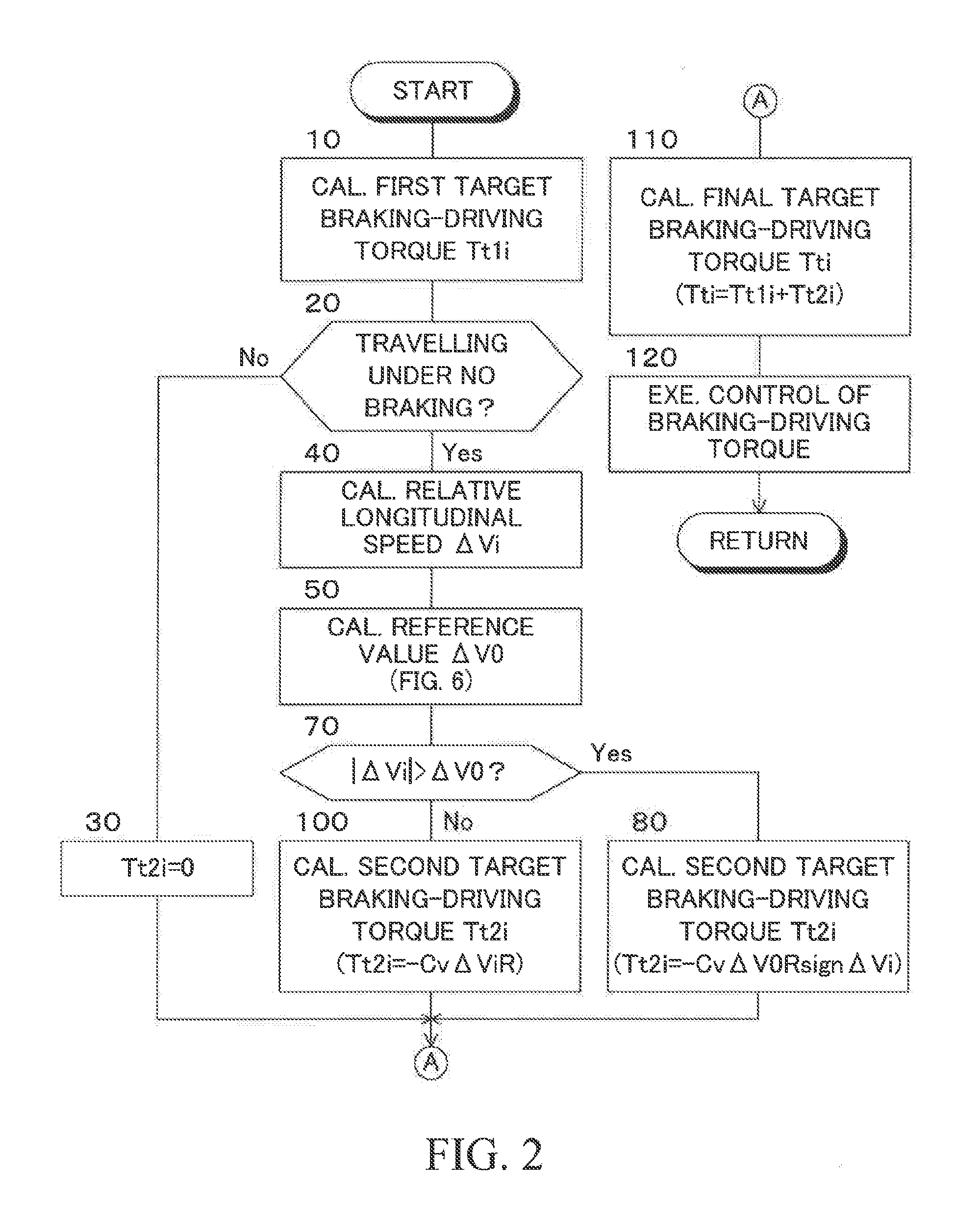
[0092]As is understood from comparing FIG. 4 with FIG. 2, in the third embodiment, after step 50 is completed, the control proceeds to step 60 and after step 60 is completed, the control proceeds to step 70. The steps other than step 60 are conducted in the same manner as in the first embodiment.

[0093]In step 60, longitudinal speeds ΔVi of the wheels relative to the vehicle body 18 calculated in step 40 are frequency analyzed to derive principal frequencies fm of longitudinal speeds ΔVi. Further, coefficient Cv is calculated by referring to a map shown in FIG. 7 based on each of principal frequencies fm. As shown in FIG. 7, coefficient Cv is calculated to be a positive value Cvmax when principal frequencies fm are values within a specific frequency rang...


PUM


Abstract

An electric vehicle includes electric motors imparting driving forces to the corresponding driving wheels, a brake device imparting braking forces to the driving wheels, a control unit which calculates final target braking-driving forces (Tti) of the driving wheels and controls the electric motors and the brake device so that braking-driving forces of the driving wheels conform to the corresponding final target braking-driving forces. The control unit calculates longitudinal speeds (ΔVi) of the wheels relative to a vehicle body; calculates target correction amounts (Tt2i) of the target braking-driving forces for reducing in magnitude longitudinal speeds of the driving wheels relative to the vehicle body based on the relative longitudinal speeds; and corrects the target braking-driving forces (Tt1i) with the target correction amounts (Tt2i) to calculate final target braking-driving forces (Tti) of the driving wheels.

Description

CROSS-REFERENCE TO RELATED APPLICATIONS[0001]The disclosure of Japanese Patent Application No. JP 2015-151318 filed on Jul. 30, 2015 is incorporated herein by reference in its entirety.BACKGROUND[0002]1. Technical Field[0003]The present disclosure relates to an electric vehicle having electric motors imparting driving forces to corresponding driving wheels independently from each other.[0004]2. Description of the Related Art[0005]As an electric vehicle such as an electric automobile, an electric vehicle is well-known which has driving wheels driven by corresponding electric motors. In such an electric vehicle, under a normal travelling situation, a target braking-driving force of each wheel is calculated and each electric motor and a brake device are controlled with quick response so that an actual braking-driving force of each wheel conforms to the corresponding target braking-driving force.[0006]Incidentally, in an electric vehicle, since, as in a vehicle which has an internal com...

Claims


Application Information

Patent Timeline
IPC IPC(8): B60W30/02B60K1/02B60L11/18B60W10/08B60L7/14B60G7/00B60W10/184
CPCB60W30/025B60G7/001B60K1/02B60W10/184B60W10/08B60L7/14B60W2520/28B60G2400/106B60G2800/91B60W2710/081B60W2710/182B60W2520/105B60L11/1803B60L15/20B60L15/2009B60T8/58B60G17/0195B60G2300/50B60G2800/22B60K7/0007B60K17/356B60L7/18B60L2220/44B60L2240/12B60L2240/22B60L2240/423B60L50/51Y02T10/64Y02T10/70Y02T10/72
Inventor FUKUDOME, HIDEKI
Owner TOYOTA JIDOSHA KK
Why Eureka
Try Eureka