Delaminatable container, method of checking the same for a pinhole, and method of processing the same
a technology of laminatable containers and pinholes, applied in the direction of caps, liquid handling, instruments, etc., can solve problems such as difficult to secure, and achieve the effect of reducing time and inhibiting air leakag
- Summary
- Abstract
- Description
- Claims
- Application Information
AI Technical Summary
Benefits of technology
Problems solved by technology
Method used
Image
Examples
first embodiment
1. First Embodiment
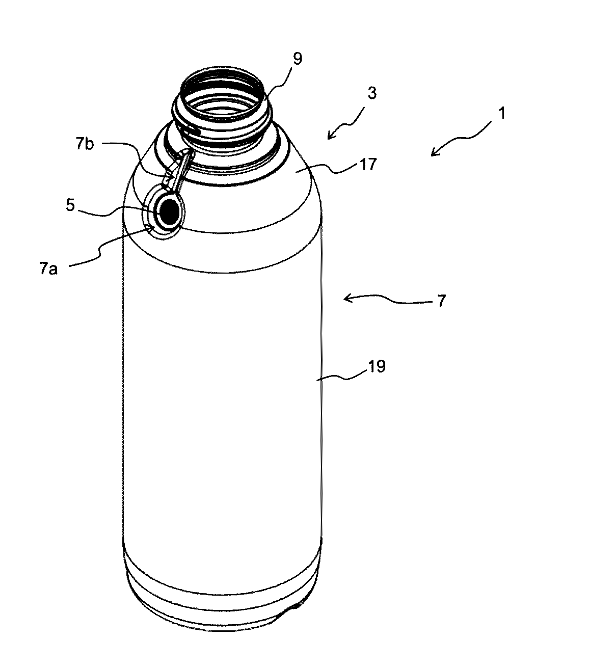
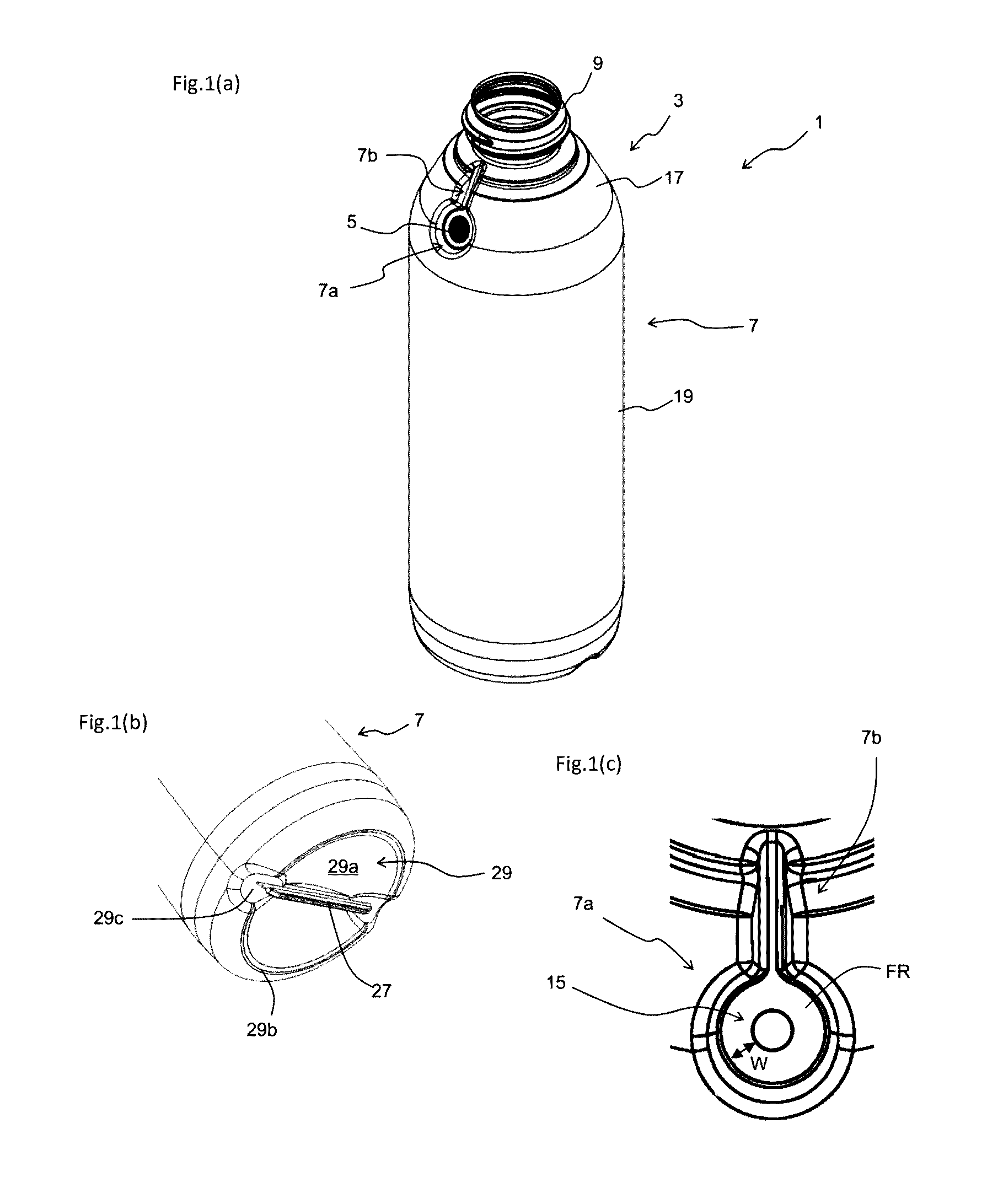
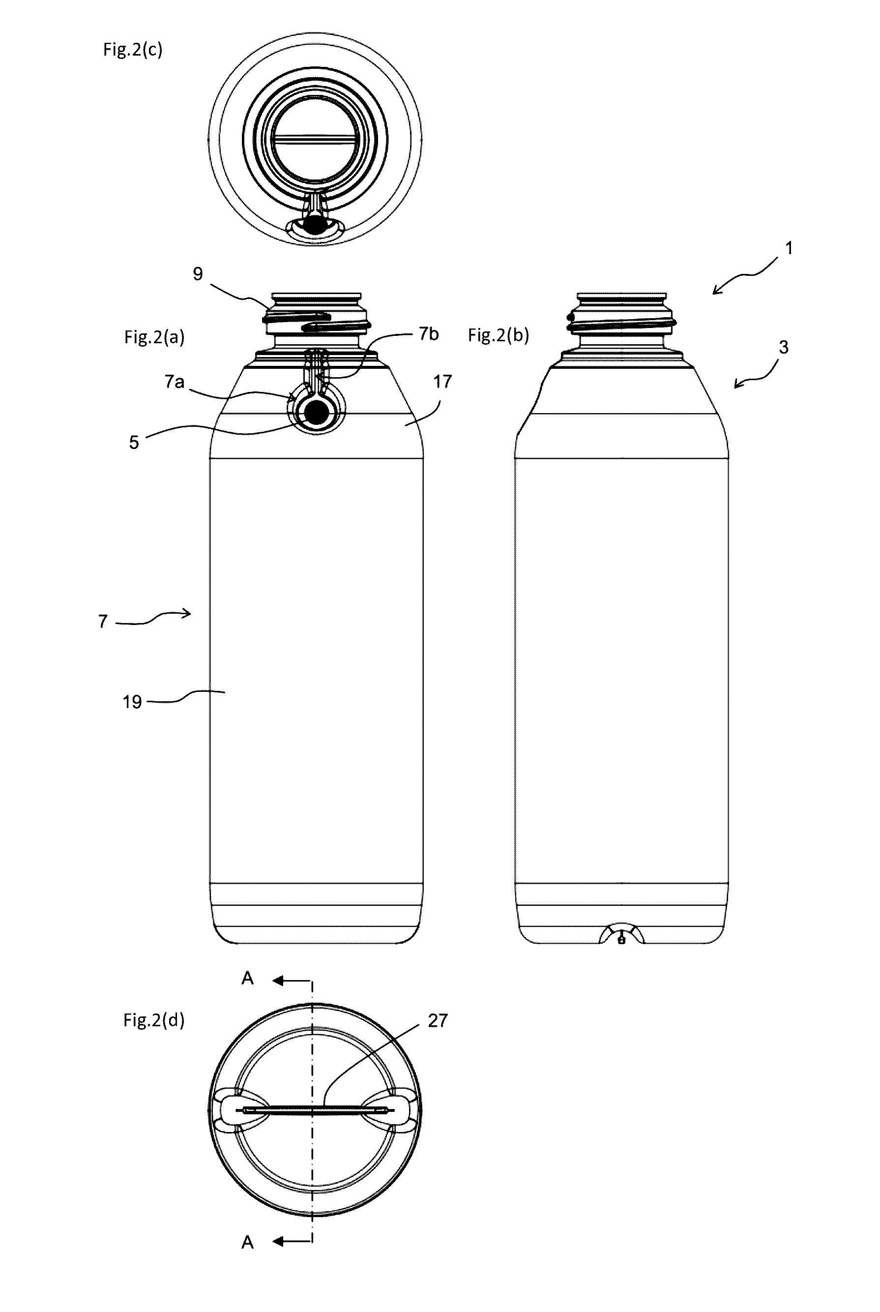
[0090]As illustrated in FIGS. 1 through 2, a delaminatable container 1 in the first embodiment of the present invention is provided with a container body 3 and a valve member 5. The container body 3 is provided with a storage portion 7 to store the contents and a mouth 9 to deliver the contents from the storage portion 7.
[0091]As illustrated in FIG. 3, the container body 3 is provided with an outer layer 11 and an inner layer 13 in the storage portion 7 and the mouth 9. An outer shell 12 is composed of the outer layer 11 and an inner bag 14 is composed of the inner layer 13. Due to delamination of the inner layer 13 from the outer layer 11 with a decrease in the contents, the inner bag 14 delaminates from the outer shell 12 to be shrunk.
[0092]As illustrated in FIG. 4, the mouth 9 is equipped with external threads 9d. To the external threads 9d, a cap, a pump, or the like having internal threads is mounted. FIG. 4 partially illustrates a cap 23 having an inner ring...
second embodiment
2. Second Embodiment
[0170]Then, with reference to FIG. 15, a delaminatable container 1 in a second embodiment of the present invention is described. The delaminatable container 1 in the present embodiment has the layer structure and the functions same as those in the first embodiment, whereas it is different in a specific shape. The delaminatable container 1 in the present embodiment is particularly different in the configuration of and around a valve member mounting recess 7a from the first embodiment, and thus the descriptions are given below mainly on this point.
[0171]As illustrated in FIG. 15(a), the delaminatable container 1 in the present embodiment is structured by coupling a mouth 9 to a main portion 19 by a shoulder portion 17. While the bent portion 22 is provided in the shoulder portion 17 in the first embodiment, the shoulder portion 17 is not provided with a bent portion 22 in the present embodiment and the boundary between the shoulder portion 17 and the main portion 1...
third embodiment
3. Third Embodiment
[0173]Then, with reference to FIG. 21, a delaminatable container 1 in a third embodiment of the present invention is described. The delaminatable container 1 in the present embodiment has the layer structure and the functions same as those in the first and second embodiments, whereas it is different in the structure of a valve member 5.
[0174]Specifically, the valve member 5 in the present embodiment has a locking portion 5b provided with a pair of foundation portions 5b1 and a bridge portion 5b2 disposed between the foundation portions 5b1. An axis 5a is provided on the bridge portion 5b2.
[0175]The lid 5c is configured to substantially close the fresh air inlet 15 when the outer shell 12 is compressed and is provided with a tapered surface 5d to have a smaller cross-sectional area as coming closer to the axis 5a. An inclination angle β of the tapered surface 5d illustrated in FIG. 21(c) is preferably from 15 to 45 degrees to a direction D in which the axis 5a exte...
PUM
| Property | Measurement | Unit |
|---|---|---|
| Pressure | aaaaa | aaaaa |
| Angle | aaaaa | aaaaa |
| Angle | aaaaa | aaaaa |
Abstract
Description
Claims
Application Information
 - R&D
- Intellectual Property
- Life Sciences
- Materials
- Tech Scout
- Unparalleled Data Quality
- Higher Quality Content
- 60% Fewer Hallucinations
Browse by: Latest US Patents, China's latest patents, Technical Efficacy Thesaurus, Application Domain, Technology Topic, Popular Technical Reports.
© 2025 PatSnap. All rights reserved.Legal|Privacy policy|Modern Slavery Act Transparency Statement|Sitemap|About US| Contact US: help@patsnap.com


