Liquid-cool light emitting diodes light

a light-emitting diode and liquid-cool technology, applied in the direction of point-like light sources, lighting and heating apparatus, light sources, etc., can solve the problems of large consumption of electric power, large space occupation, and the inability of heat dissipation fins to be attached to leds, etc., to achieve small emitting area, low cost, and high efficiency

Inactive Publication Date: 2017-02-02
NAT CENT UNIV
View PDF5 Cites 8 Cited by
  • Summary
  • Abstract
  • Description
  • Claims
  • Application Information

AI Technical Summary

Benefits of technology

[0017]The primary object of the present invention is to provide a liquid-cool Light Emitting Diodes light with high efficiency for removal of heat generated from the Light Emitting Diodes, while the liquid-cool Light Emitting Diodes light occupies less space and small emitting area.

Problems solved by technology

However, these lights consume significant electric power and generate heat of high temperature which has to be removed efficiently so as to protect the lights.
The lights together with their bases or casings, and the heat dissipation devices occupy space.
Nevertheless, the heat removal of the LEDs is the main concern when using LEDs because usually hundreds LEDs are used.
Although the conventional way to remove the heat can be made by using heat dissipation fins, the heat dissipation fins cannot attached to the LEDs when the LEDs are used on a large display screen.

Method used


Image

  • Liquid-cool light emitting diodes light
  • Liquid-cool light emitting diodes light
  • Liquid-cool light emitting diodes light

Examples


Embodiment Construction

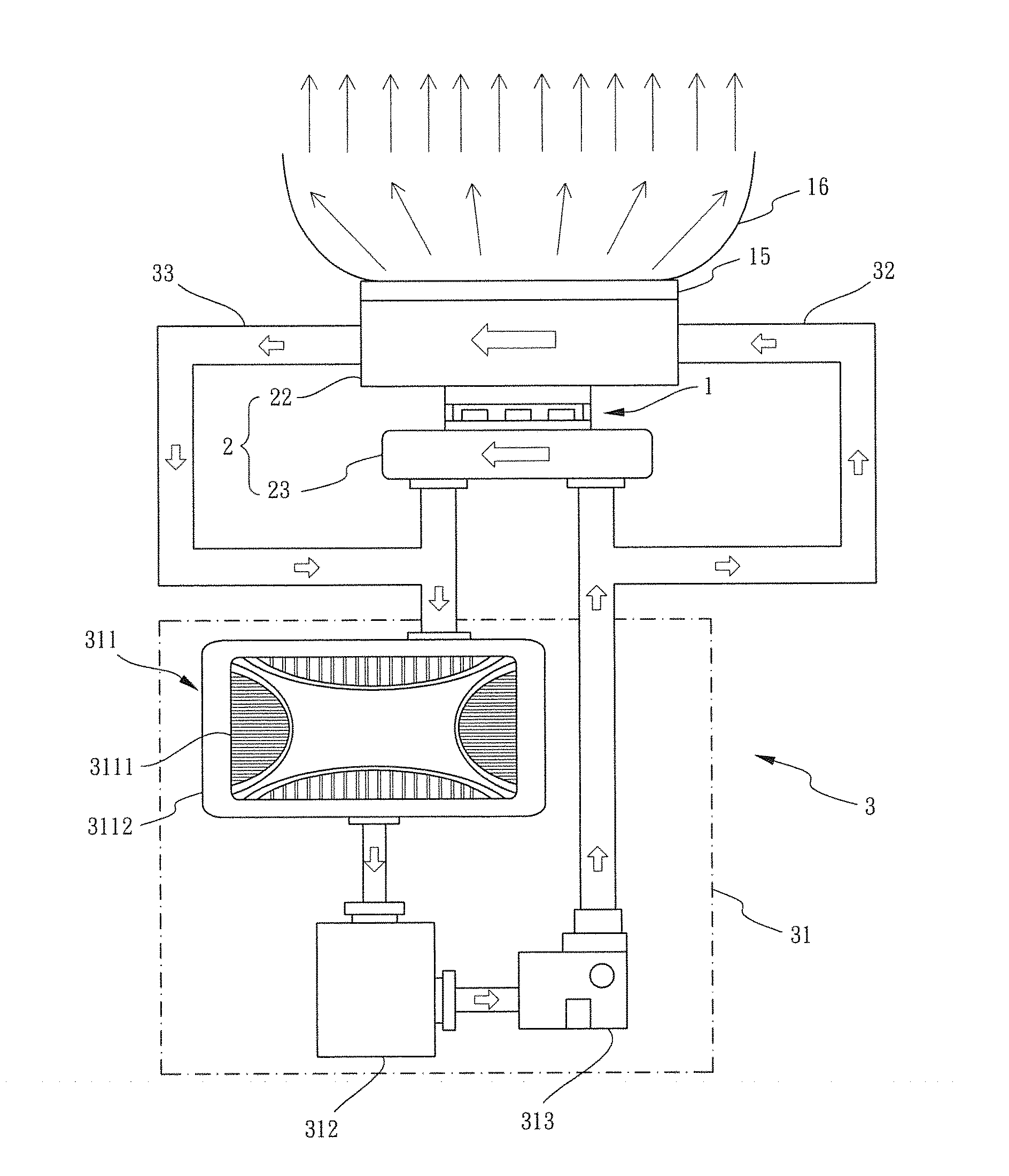
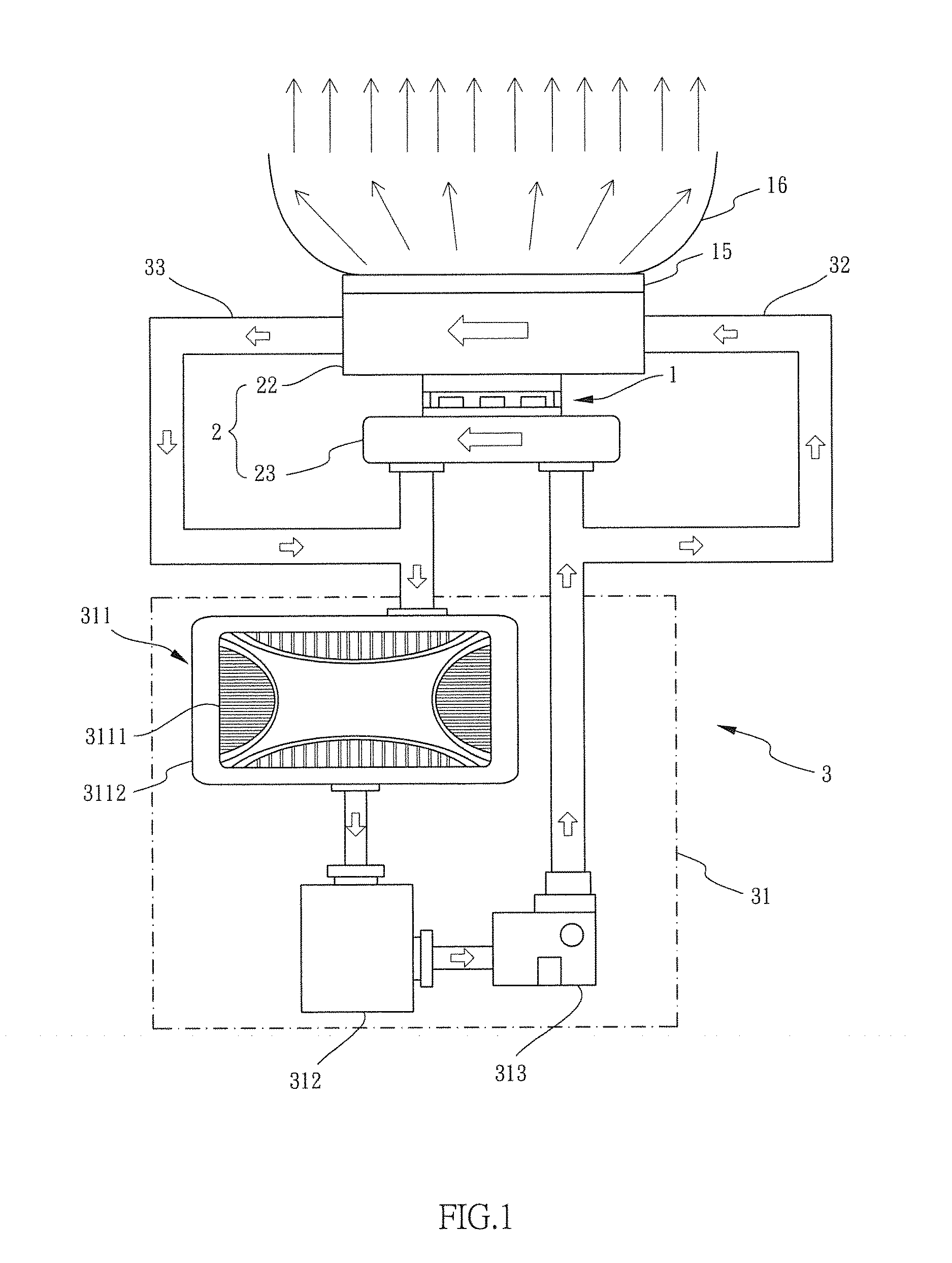
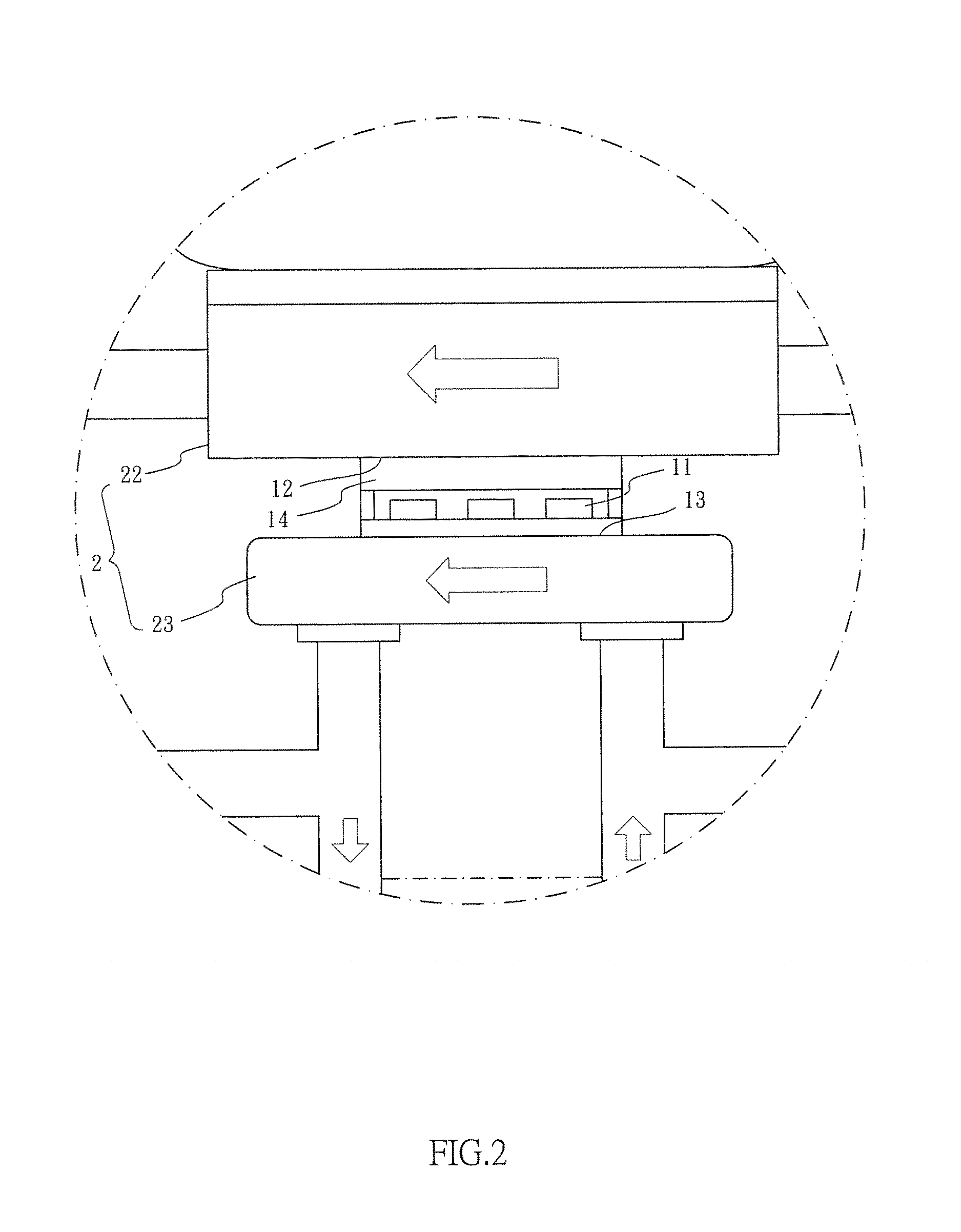
[0023]Referring to FIGS. 1 to 2, the liquid-cool Light Emitting Diodes light of the present invention comprises a light source 1 having multiple Light Emitting Diode units 11 (LED units). The light source 1 has a first face 12 and a second face 13. A cooling unit 2 has a first cooling member 22 and a second cooling member 23, wherein the first cooling member 22 is connected to the first face 12, and the second cooling member 23 is connected to the second face 13. A cooling system 3 has a cooling device 31, a first path 32 and a second path 33. The first path 32 of the cooling device 31 is connected to the two respective first ends of the first and second cooling members 22, 23, and the second path 33 of the cooling device 31 connected to the two respective second ends of the first and second cooling members 22, 23.

[0024]Heat generated from the LED units 11 is transferred to the cooling device 2 by cooling liquid circulates in the cooling system 3 and the cooling device 2. The heat i...


PUM


Abstract

A liquid-cool Light Emitting Diodes light includes a light source having multiple LED units. A cooling unit includes a first cooling member connected to the first face of the light source, and a second cooling member connected to the second face of the light source. A cooling system has a cooling device, a first path and a second path. The first path of the cooling device is connected to two respective first ends of the first and second cooling members. The second path of the cooling device is connected to two respective second ends of the first and second cooling members. The heat generated from the LED units is efficiently removed and with small emitting area.

Description

BACKGROUND OF THE INVENTION[0001]1. Fields of the Invention[0002]The present invention relates to a Light Emitting Diodes light, and more particularly, to a liquid-cool Light Emitting Diodes light.[0003]2. Descriptions of Related Art[0004]The conventional lighting device generally comprises multiple lights which provide sufficient illumination. However, these lights consume significant electric power and generate heat of high temperature which has to be removed efficiently so as to protect the lights. In other words, multiple heat dissipation devices are required to be cooperated with the multiple lights. The lights together with their bases or casings, and the heat dissipation devices occupy space.[0005]Light Emitting Diodes (LEDs) are developed to improve the shortcomings mentioned above, the LEDs are compact and provide sufficient brightness. Nevertheless, the heat removal of the LEDs is the main concern when using LEDs because usually hundreds LEDs are used. Although the convent...

Claims


Application Information

Patent Timeline
Patent Type & Authority Applications(United States)
IPC IPC(8): F21V29/56F21K99/00F21V29/503
CPCF21V29/56F21Y2101/02F21K9/56F21V29/503F21V29/506F21V29/59F21K9/64F21Y2115/10
Inventor SUN, CHING-CHERNGCHANG, YU-YUCHUNG, YI-JING
Owner NAT CENT UNIV
Why Eureka
Try Eureka