Woven tubular thermal sleeve and method of construction thereof

Active Publication Date: 2017-02-09
FEDERAL MOGUL POWERTAIN LLC
View PDF1 Cites 6 Cited by
  • Summary
  • Abstract
  • Description
  • Claims
  • Application Information

AI Technical Summary

Benefits of technology

[0007]One aspect of the invention provides a thermal sleeve for routing and protecting elongate members. The sleeve has an elongate, tubular woven wall extending along a central axis between opposite open ends with an outer layer of reflective foil fixed thereto. The wall is woven with warp yarns extending parallel to the central axis and fill yarns extending transversely to the warp yarns. The fill yarns are provided as first fill yarn and second fill yarn, wherein the first fill yarn is bundled with the second fill yarn in side-by-side abutting relation. As such, the first fill yarn and second fill yarn are woven together as a single pick, thereby forming disc

Problems solved by technology

However, problems with the known protective sleeves have proven difficult to overcome; namely, the braided sleeves are typically loose and take on a flat profile, while the protective woven sleeves typically have a very tight weave structure to prevent the woven yarns from shifting relative to one another, and thus, the woven sleeves are generally very stiff.
Both conditions present potential problems in use.
With the braided sleeves, the sleeves are difficult to install as a result of being generally flat, and also have prob

Method used


Image

  • Woven tubular thermal sleeve and method of construction thereof
  • Woven tubular thermal sleeve and method of construction thereof
  • Woven tubular thermal sleeve and method of construction thereof

Examples


Example

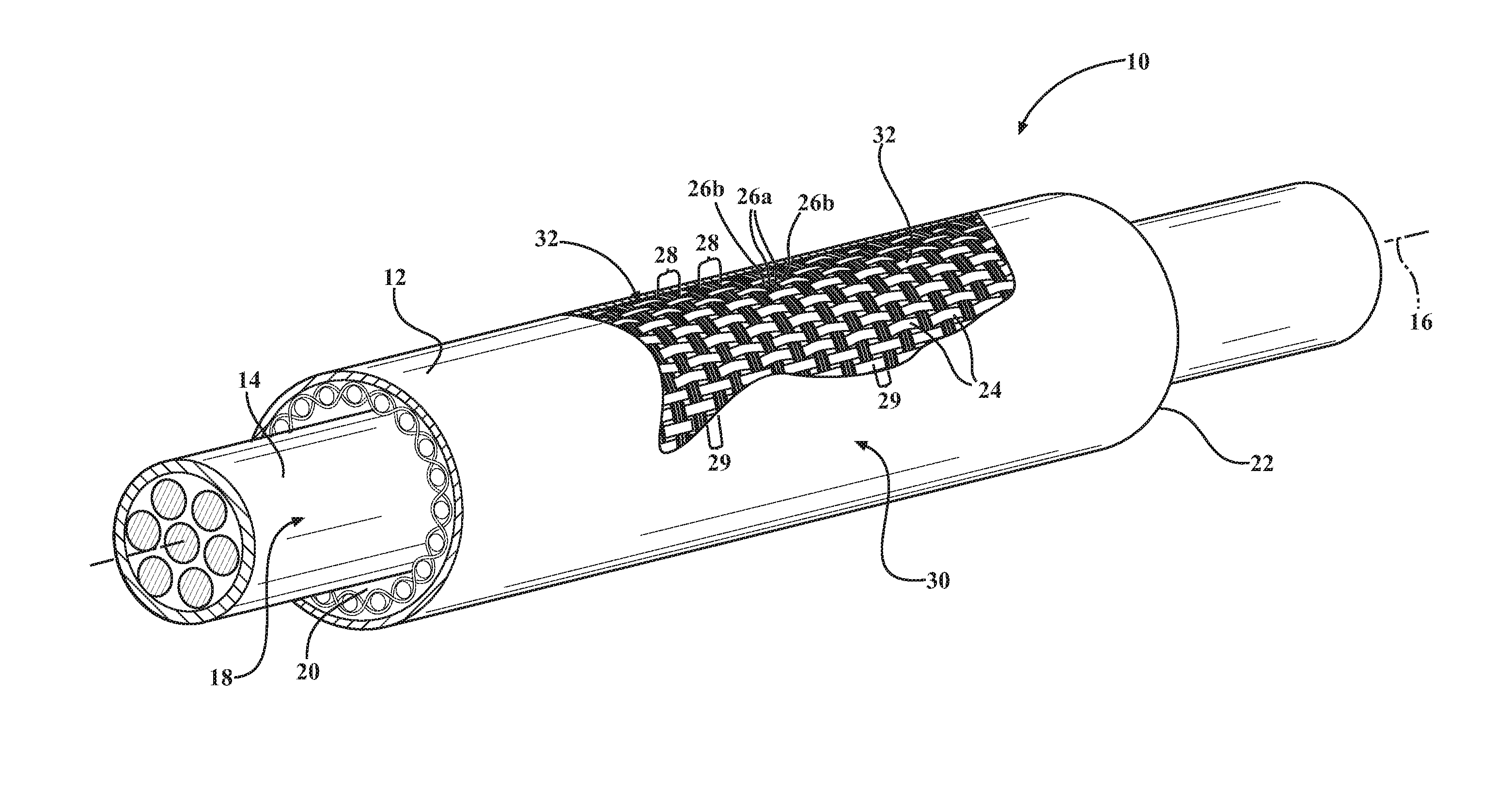
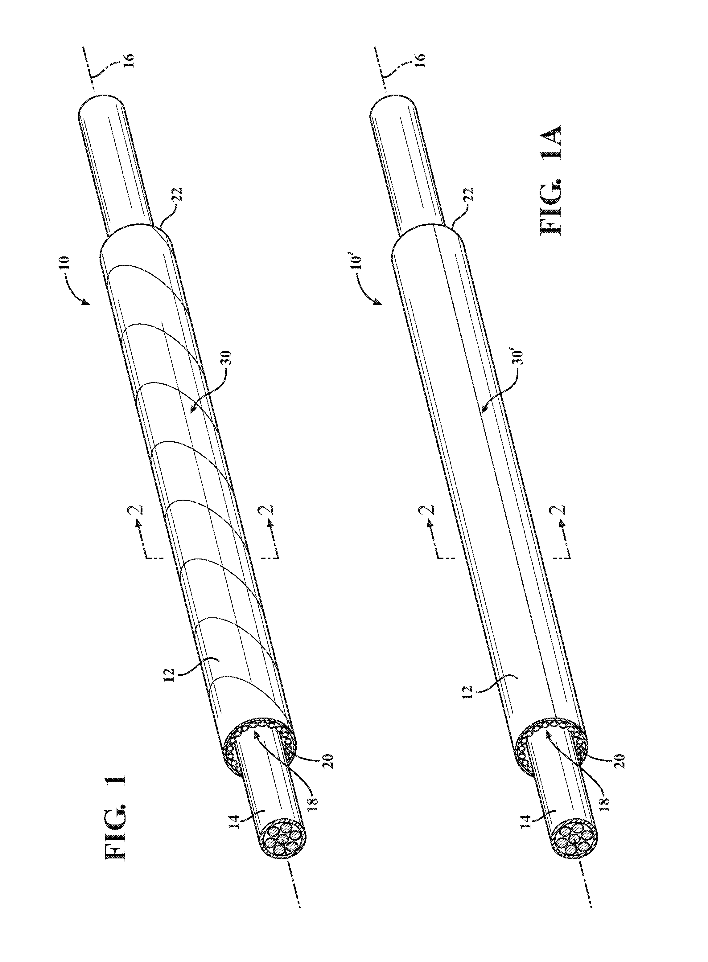
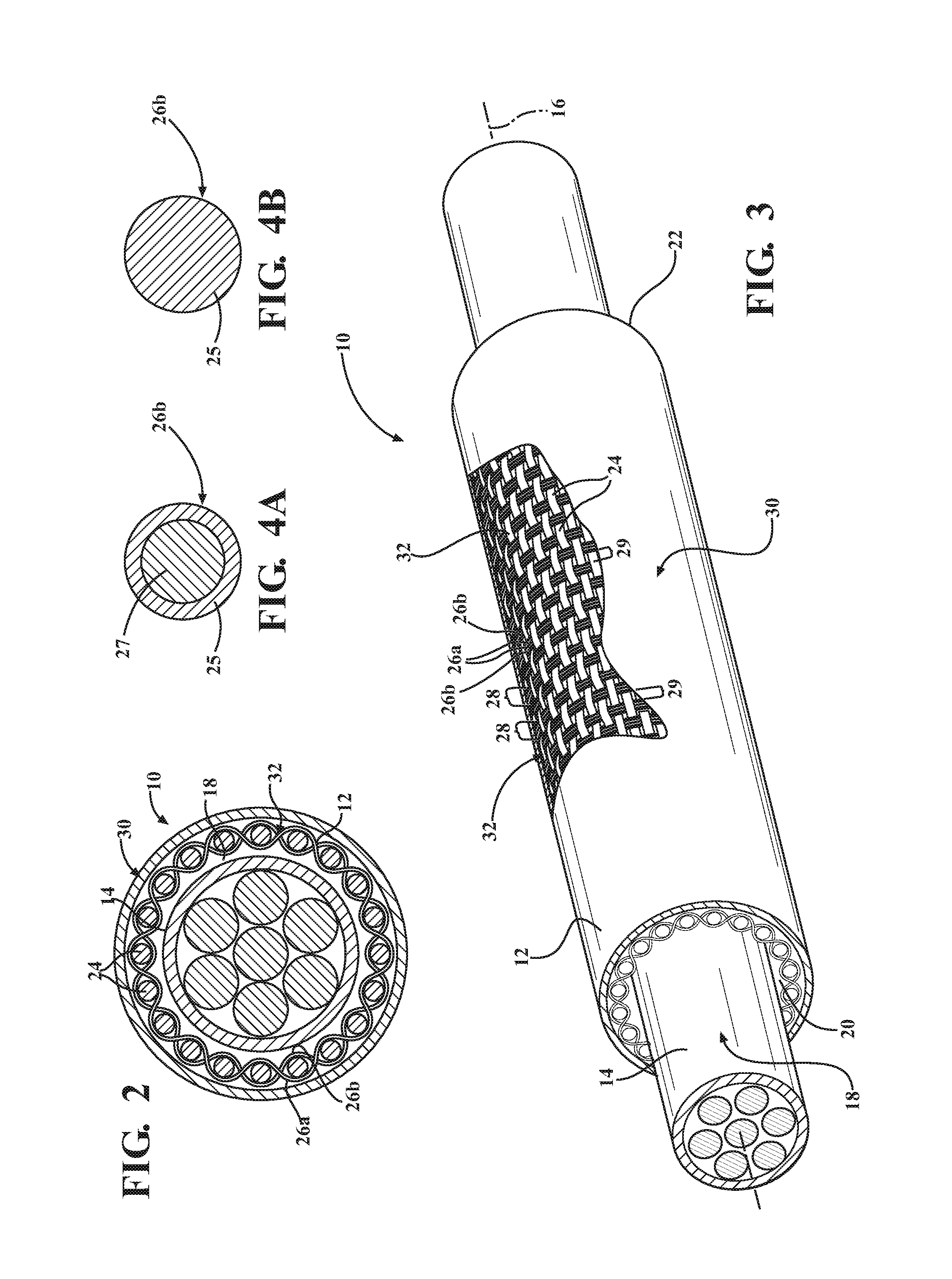
[0031]Referring in more detail to the drawings, FIG. 1 shows a schematic representation of a thermally protective tubular woven sleeve, referred to hereafter as sleeve 10, constructed in accordance with one aspect of the invention. It is to be understood that by tubular, it is meant that the sleeve 10 has a circumferentially continuous wall 12, and that it does not have free lengthwise extending side edges. The sleeve 10 is intended for routing and protecting elongate members 14, such as wires, a wire harness, or conduit, for example, from exposure to abrasion and the ingress of contamination, debris and the like, while also shielding the elongate members 14 against exposure to heat. The elongate wall 12 extends lengthwise along a central axis 16 and bounds a circumferentially enclosed cavity 18 that extends along the central axis 16 between opposite open ends 20, 22. The wall 12 is woven with warp yarns 24 and fill yarns, wherein the fill yarns include first fill yarn 26a and secon...


PUM

PropertyMeasurementUnit
Strengthaaaaaaaaaa
Melting pointaaaaaaaaaa
Heataaaaaaaaaa

Abstract

A thermal sleeve for routing and protecting elongate members and method of construction thereof are provided. The sleeve has a tubular woven wall extending along a central axis between opposite open ends with an outer reflective foil layer fixed thereto. The wall is woven with lengthwise extending warp yarns and circumferentially extending fill yarns. The fill yarns include first and second fill yarns bundled in side-by-side abutting relation as a single pick, thereby forming discrete single pick bundles in axially spaced relation from one another. The first fill yarn is provided as a standard monofilament, while the second fill yarn is provided having a low melt material melted and bonded to the abutting first fill yarn and to portions of the abutting warp yarns, wherein the spaces between the discrete bundles remain substantially free of melted material, thereby further enhancing longitudinal flexibility of the sleeve.

Description

CROSS-REFERENCE TO RELATED APPLICATION[0001]This application claims the benefit of U.S. Provisional Application Ser. No. 62 / 200,783, filed Aug. 4, 2015, which is incorporated herein by reference in its entirety.BACKGROUND OF THE INVENTION[0002]1. Technical Field[0003]This invention relates generally to textile sleeves for protecting elongate members, and more particularly to thermally protective woven tubular sleeves.[0004]2. Related Art[0005]It is known to contain elongate members, such as wires, wire harnesses, cables and conduits of various types, in both tubular braided and woven textile sleeves having a reflective foil outer layer bonded thereto, such as in automobiles, aircraft and aerospace craft, to provide protection to the elongate members against abrasion, fluid and thermal affects. However, problems with the known protective sleeves have proven difficult to overcome; namely, the braided sleeves are typically loose and take on a flat profile, while the protective woven sl...

Claims


Application Information

Patent Timeline
IPC IPC(8): B32B1/08H01B7/17B32B5/02B32B15/14F16L57/06D03D25/00
CPCB32B1/08F16L57/06D03D25/005B32B5/024B32B15/14B32B2605/00D10B2401/041B32B2262/101B32B2262/0284B32B2307/304H01B7/17D03D3/02D10B2101/06D10B2331/04H02G3/0412H02G3/0481B60R16/0207H02G3/04D03D15/267D03D15/47D03D15/587D03D1/0043D03D15/292
Inventor MALLOY, CASSIE M.GE, QINGTONGGAO, TIANQIMUELE, EDGARWINTERS, DANNY
Owner FEDERAL MOGUL POWERTAIN LLC
Why Eureka
Try Eureka