Turboprop engine assembly with combined engine and cooling exhaust

a technology of combined engine and exhaust, which is applied in the direction of machines/engines, efficient propulsion technologies, mechanical apparatuses, etc., can solve the problems of stubs causing drag on the engine, and materials typically represent significant costs

Active Publication Date: 2017-02-09
PRATT & WHITNEY CANADA CORP
View PDF4 Cites 22 Cited by
  • Summary
  • Abstract
  • Description
  • Claims
  • Application Information

AI Technical Summary

Benefits of technology

[0006]In another aspect, there is provided a turboprop engine assembly for an aircraft, the turboprop engine assembly comprising: an internal combustion engine having a liquid coolant system, the internal combustion engine drivingly engaged to a propeller; a turbine section having an inlet in fluid communication with an outlet of the internal combustion engine, the turbine section including at least one turbine compounded with the internal combustion engine; an air duct having an inlet positioned aft of the propeller and an outlet positioned aft of the inlet, the inlet and outlet both in fluid communication with the an environment of the aircraft; a heat exchanger in fluid communication with the liquid coolant system and located in the air duct, at least part of a fluid communication between the inlet and outlet of the air duct being performed through the heat exchanger; and an exhaust duct in fluid communication with an exhaust of the turbine section, the exhaust duct having an outlet positioned within the air duct downstream of the fan and upstream of the outlet of the air duct, the outlet of the exhaust duct spaced inwardly from a peripheral wall of the air duct so that, in use, a flow of cooling air through the air duct surrounds a flow of exhaust gases out of the exhaust duct, an open cross-sectional area of the outlet of the exhaust duct being smaller than an open cross-sectional area of the air duct around the outlet of the exhaust duct.

Problems solved by technology

Such an exhaust stub usually creates drag for the engine.
Such materials typically represent significant costs.

Method used


Image

  • Turboprop engine assembly with combined engine and cooling exhaust
  • Turboprop engine assembly with combined engine and cooling exhaust
  • Turboprop engine assembly with combined engine and cooling exhaust

Examples


Embodiment Construction

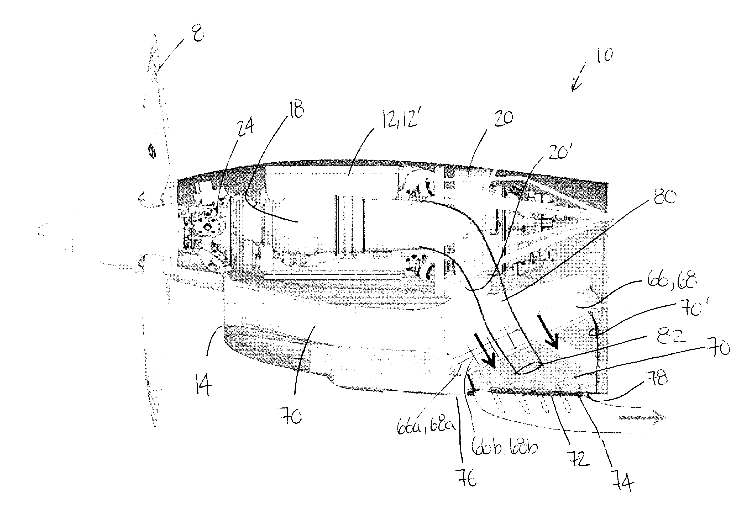
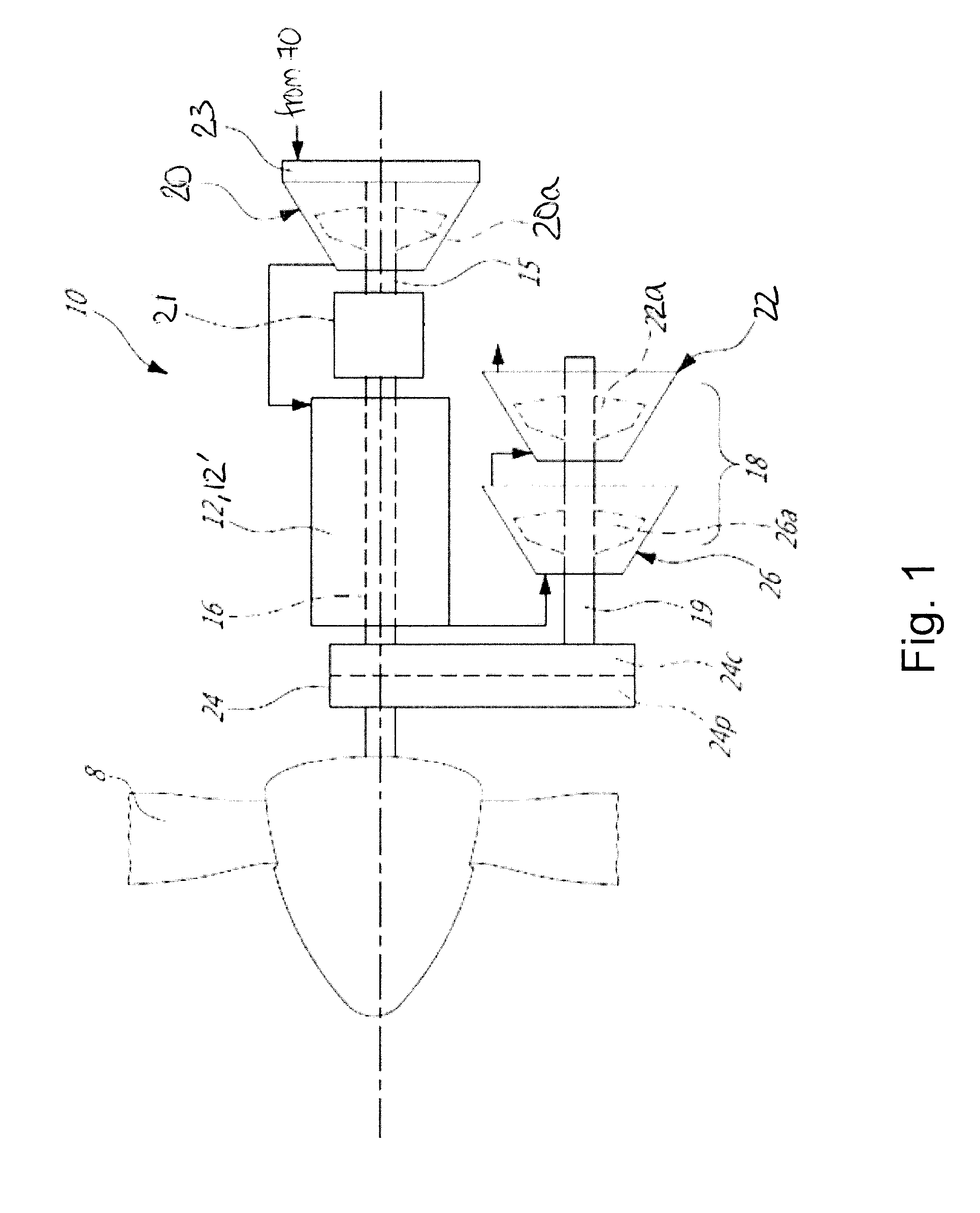
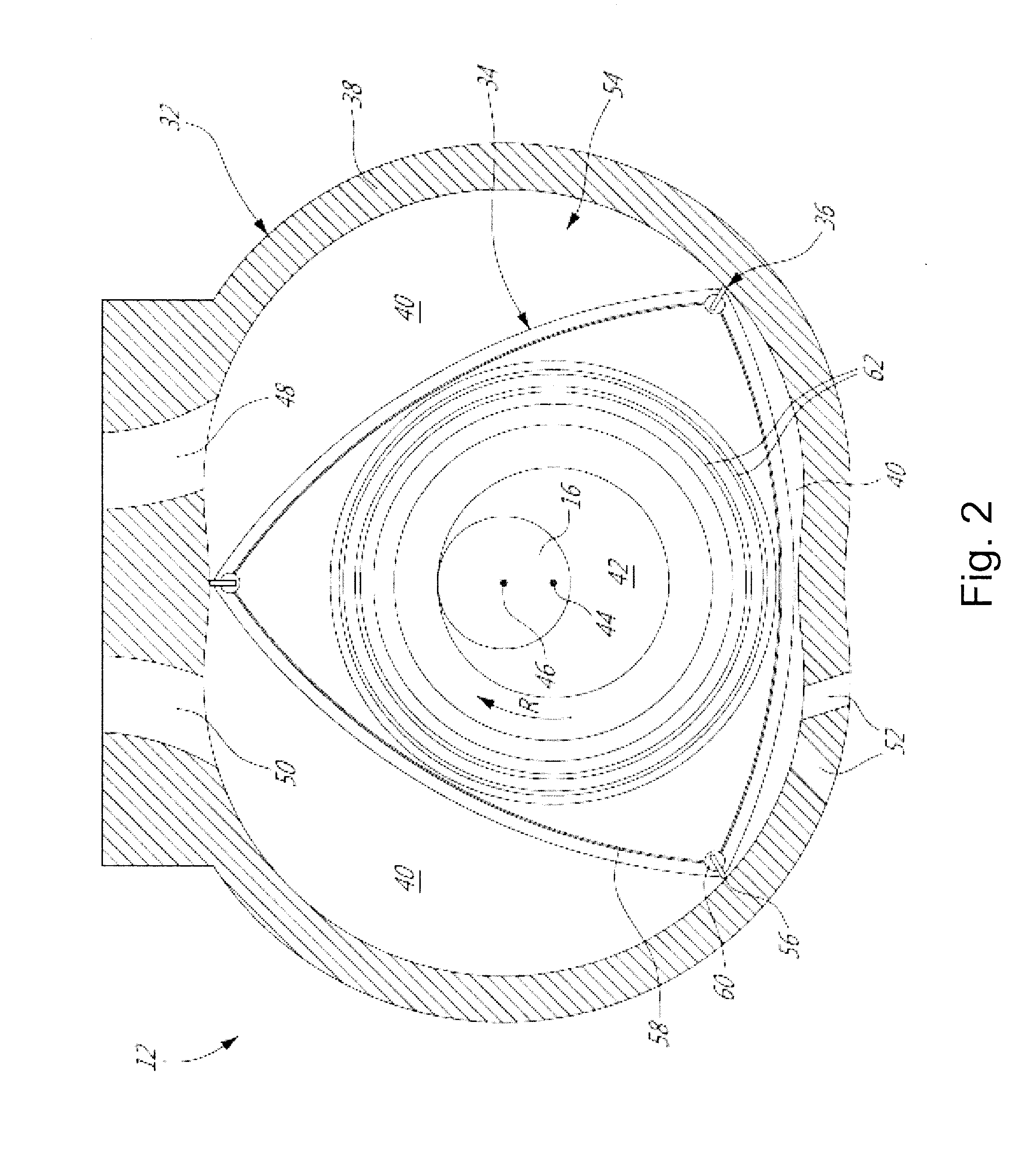
[0013]FIG. 1 illustrates a compound engine assembly 10 which is configured as a turboprop engine, in accordance with a particular embodiment. In the embodiment shown, the compound engine assembly 10 includes a liquid cooled heavy fueled multi-rotor rotary intermittent combustion engine core 12′. As will be detailed below, other configurations for the engine core 12′ are also possible.

[0014]The engine core 12′ has an engine shaft 16 driven by the internal combustion engine(s) 12 and driving a rotatable load, which is shown here as a propeller 8. It is understood that the compound engine assembly 10 may alternately be configured to drive any other appropriate type of load, including, but not limited to, one or more generator(s), drive shaft(s), accessory(ies), rotor mast(s), compressor(s), or any other appropriate type of load or combination thereof. The compound engine assembly 10 further includes a compressor 20, and a turbine section 18 compounding power with the engine core 12′.

[0...


PUM


Abstract

A turboprop engine assembly for an aircraft, including an internal combustion engine having a liquid coolant system, an air duct in fluid communication with an environment of the aircraft, a heat exchanger received within the air duct having coolant passages in fluid communication with the liquid coolant system and air passages air passages in fluid communication with the air duct, and an exhaust duct in fluid communication with an exhaust of the internal combustion engine. The exhaust duct has an outlet positioned within the air duct downstream of the heat exchanger and upstream of an outlet of the air duct, the outlet of the exhaust duct spaced inwardly from a peripheral wall of the air duct. In use, a flow of cooling air surrounds a flow of exhaust gases. A method of discharging air and exhaust gases in an turboprop engine assembly having an internal combustion engine is also discussed.

Description

CROSS-REFERENCE TO RELATED APPLICATIONS[0001]This application claims priority from U.S. application No. 62 / 202,275 filed Aug. 7, 2015, the entire contents of which are incorporated by reference herein.TECHNICAL FIELD[0002]The application relates generally to compound engine assemblies and, more particularly, to such assemblies configured as turboprop engines.BACKGROUND OF THE ART[0003]Turboprop engine typically have an engine exhaust which is directed to the environment of the aircraft, typically through an exhaust duct and stub to mix it with ambient air. Such an exhaust stub usually creates drag for the engine.[0004]Ducts and other structure in contact with the exhaust flow must typically be made of materials able to withstand significantly high temperatures. Such materials typically represent significant costs.SUMMARY[0005]In one aspect, there is provided a turboprop engine assembly for an aircraft, the turboprop engine assembly comprising: an internal combustion engine having a ...

Claims


Application Information

Patent Timeline
Patent Type & Authority Applications(United States)
IPC IPC(8): F01N3/05F02B61/04B64D33/04F02B53/14F01N13/08B64D27/10
CPCF01N3/055F01N13/082B64D27/10B64D33/04F02B2053/005F02B61/04F01N2260/022F01N2270/02F02B53/14F02K1/386F02C5/00F02C6/206F02C7/18F05D2260/213B64D27/02B64D27/08B64D33/10Y02T50/60
Inventor JULIEN, ANDRETHOMASSIN, JEANDUSSAULT, SERGE
Owner PRATT & WHITNEY CANADA CORP
Why Eureka
Try Eureka