Anti-splitting device

a technology of anti-splitting device and anti-splitting ring, which is applied in the direction of nails, pins, fastening means, etc., can solve the problems of affecting the anti-splitting device, affecting the anti-splitting effect, and affecting the stability of the anti-splitting device, so as to reduce the additional stress, reduce the effect of slipping and slipping, and facilitate the effect of insertion into the log

Inactive Publication Date: 2017-02-09
U C COATINGS CORP
View PDF3 Cites 7 Cited by
  • Summary
  • Abstract
  • Description
  • Claims
  • Application Information

AI Technical Summary

Benefits of technology

[0015]According to aspects illustrated herein, an embodiment of the present anti-splitting device includes a back plate that creates a platform to connect geometric protrusions. The protrusions can be formed in a variety of ways, including but not limited to, teeth, cylindrical cleats, frusto-conical cleats, curved blades, splittable protrusions, etc. and are preferably integrally formed with the back plate. In an embodiment having frusto-conical cleat protrusions, the cleats are tapered such that the leading end of each cleat, i.e., the portion of the cleat that first impacts the face of the material where cracks develop, are narrower than the base of each cleat, i.e., the portion of the cleat connected to the back plate, thereby enabling an easier insertion into the log or log derivative material. In some embodiments, each cleat includes a partial through-bore running from the leading end to the base to enable even distribution patterns of the fibers within the work material, e.g., timber fibers. This minimizes additional stresses created by the insertion of the anti-splitting device. Further, the hollow cleat design creates additional surface area that contacts the work material, which enables increased retention of the anti-splitting device. This increased retention will allow for increased strength as the device will remain in the desired position as forces at the crack increase.
[0016]As described above, the typical anti-splitting devices wedges that are used to prevent further expansion of the crack can create focal points of stress in the work material, which can in turn create precise points of stress. These points of str

Problems solved by technology

The nature of wood is such that, with the cyclical change of humidity, the moisture content either increases or decreases, causing fluctuations of swelling and shrinking.
These fluctuations can cause splitting in the wood across the grain, as well as along the end portions.
The core then continues to dry and shrink further, causing pressure on the “set” shell.
Exposed faces of the shell may begin to crack as the core of the log compresses further.
Cracked segments reduce the portion of timber usable for creating products such as lumber and veneer as the ends are often discarded, due to the inconsistency of timber in the regions of logs where cracking is most severe.
Although, higher grade logs have an absence of knots, the absence of knots allows cracks to develop more quickly by following straight grain patterns for the length of the timber.
While the above described methods may offer some benefits, each method is limited in certain aspects.
Metal “S” irons as well as truss plates often create staining in the wood and also require removal before wood can be processed, while other methods such as plastic clips are limited in their strength and ability to prevent newly occurring splits.
“S” irons and truss plates are also difficult to be inserted as they must be stabilized with one hand as they are driven into the face of the timber with a hammer.
Removal of “S” irons or truss plates is also very time consuming

Method used


Image

  • Anti-splitting device
  • Anti-splitting device
  • Anti-splitting device

Examples


Embodiment Construction

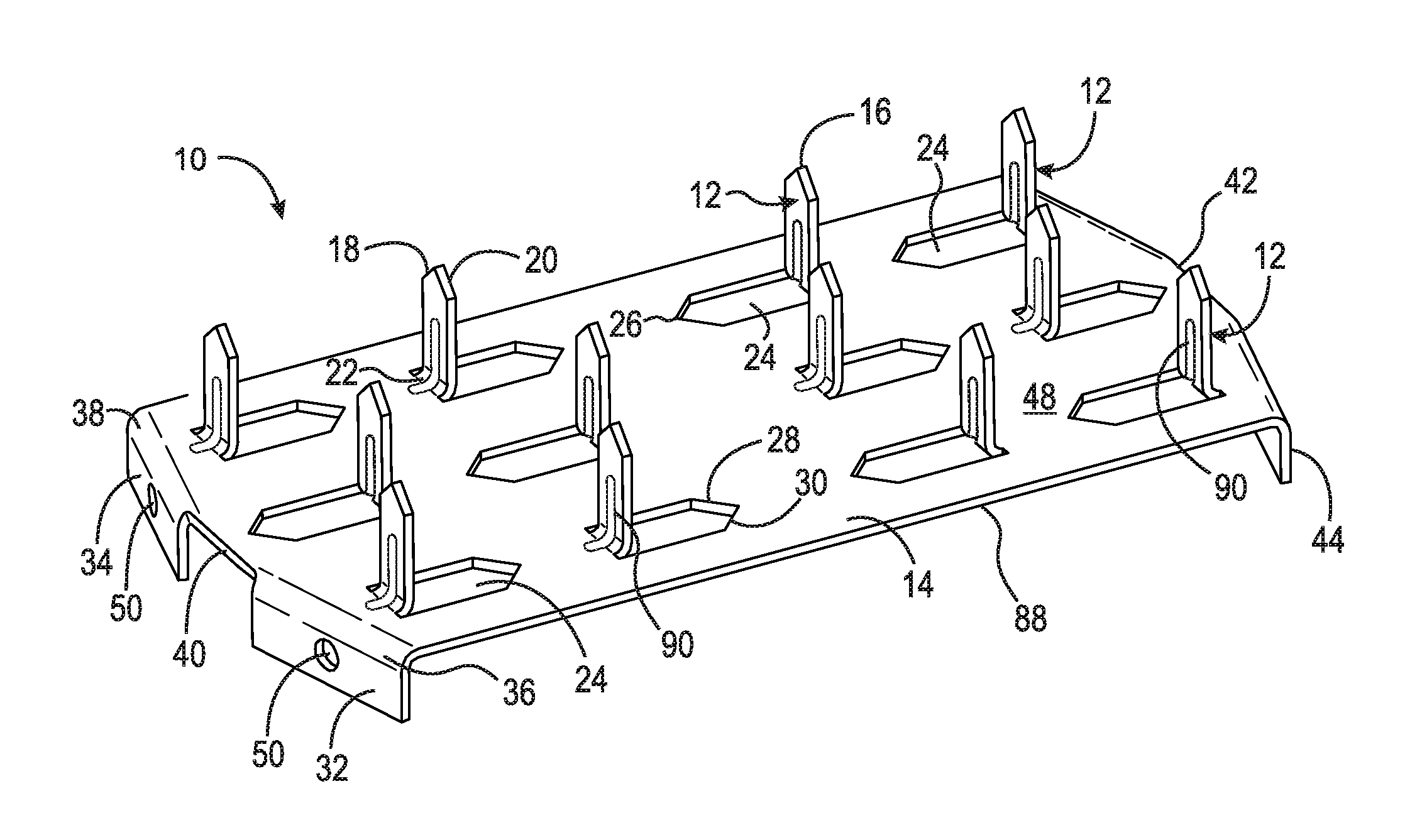
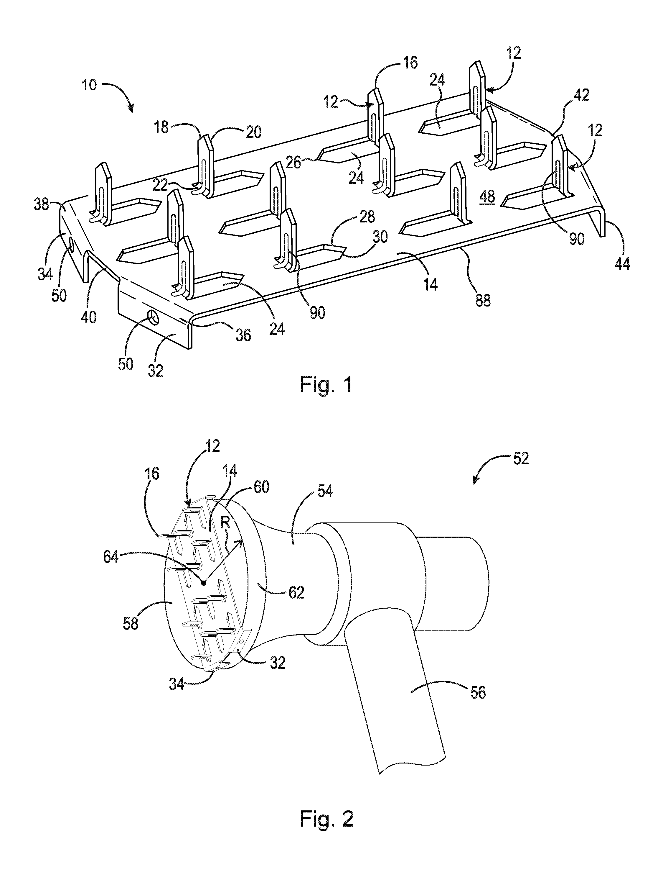
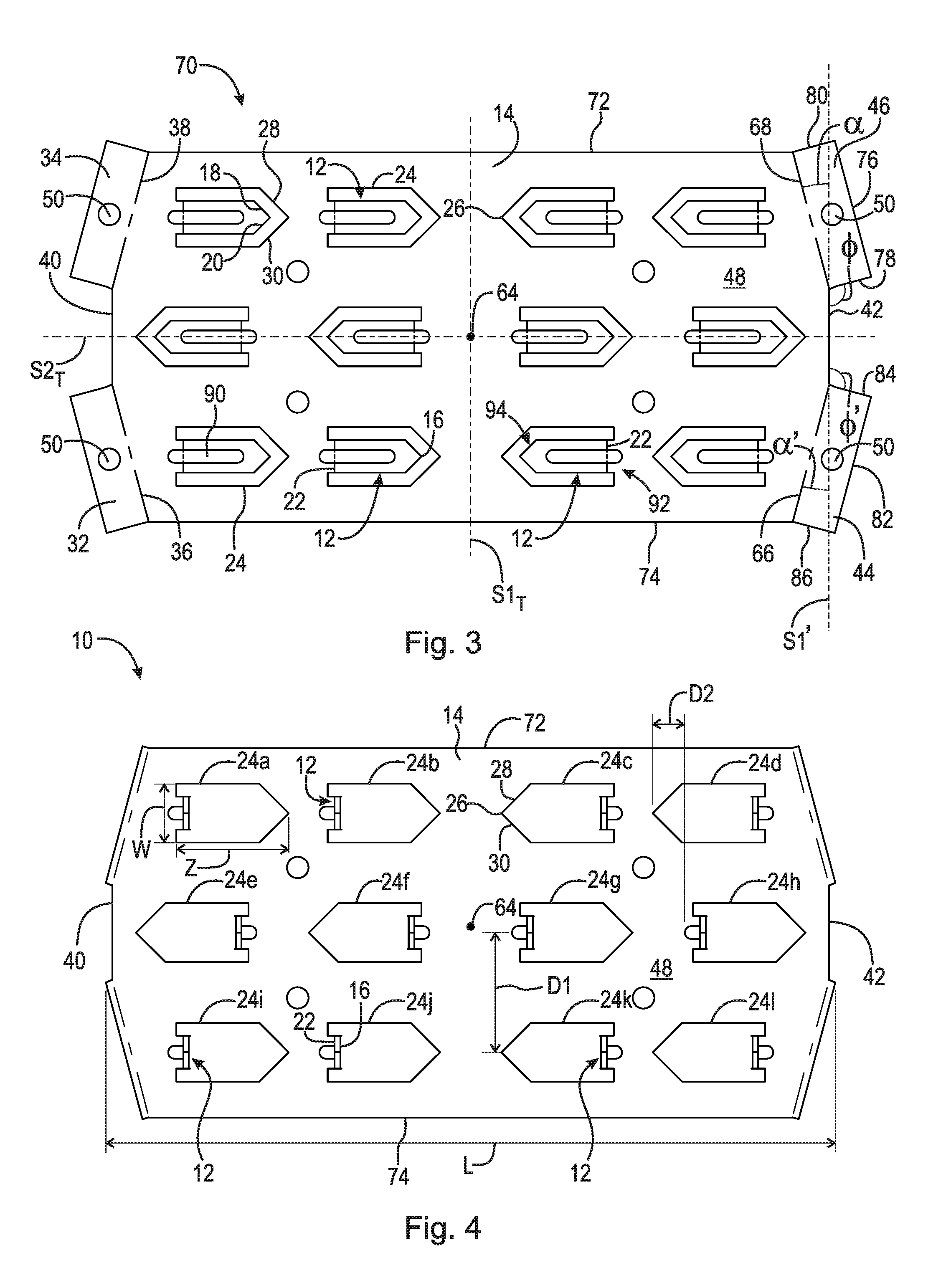
[0035]At the outset, it should be appreciated that like reference characters are used for like elements of the present embodiments or elements of like function. For the sake of clarity, only those elements and reference characters which are of relevance to the shown aspects of the respective embodiment of the present invention are shown repeatedly. In this regard, no attempt is made to show structural details of the invention in more detail than is necessary for a fundamental understanding of the invention, the description taken with the drawings making apparent to those skilled in the art how the several forms of the invention may be embodied in practice.

[0036]While the present invention is described with respect to what is presently considered to be the preferred aspects, it is to be understood that the invention as claimed is not limited to the disclosed aspects. The present invention is intended to include various modifications and equivalent arrangements within the spirit and s...


PUM


Abstract

An anti-splitting device including a base portion, a plurality of protrusions and first, second, third and fourth extensions. The base portion has a first surface and a second surface oppositely disposed relative to the first surface, a first edge and a second edge oppositely disposed relative to the first edge, and a third edge and a fourth edge oppositely disposed relative to the third edge. The plurality of protrusions are positioned about and extending from the first surface. The first extension is positioned at an intersection of the first and third edges, the second extension is positioned at an intersection of the third and second edges, the third extension is positioned at an intersection of the second and fourth edges and the fourth extension is positioned at an intersection of the fourth and first edges. Each of the first, second, third and fourth extensions extend from the second surface.

Description

CROSS-REFERENCE TO RELATED APPLICATIONS[0001]This patent application claims the benefit under 35 U.S.C. §119(e) of U.S. Provisional Patent Application No. 62 / 200,874, filed Aug. 4, 2015, which application is incorporated herein by reference.TECHNICAL FIELD[0002]The present disclosure relates generally to anti-splitting devices, more particularly to an anti-splitting device which is inserted into an end of a log, and even more particularly to an anti-splitting device which is inserted into an end of a log which may be readily removed from the log.BACKGROUND OF THE INVENTION[0003]Fallen timber and procured wood are materials central to the logging industry. Freshly cut wood naturally contains water, in both liquid and vapor forms, which makes the wood more saturated than the surrounding environment. The nature of wood is such that, with the cyclical change of humidity, the moisture content either increases or decreases, causing fluctuations of swelling and shrinking. These fluctuation...

Claims


Application Information

Patent Timeline
IPC IPC(8): F16B15/00B21G3/00
CPCF16B15/0046F16B2015/0076B21G3/005B21D53/46B21D35/001
Inventor HIGGINS, JAMES A.
Owner U C COATINGS CORP
Why Eureka
Try Eureka