Gas turbine cooling systems and methods

a technology of cooling system and gas turbine, which is applied in the direction of engine cooling apparatus, leakage prevention, engine fuction, etc., can solve the problems of limiting the life of the fir tree, the first blade is also subject to high mechanical load, etc., and achieves the effect of increasing the pressure of the cooling fluid and simplifying the gas turbine assembly and disassembly

Active Publication Date: 2017-02-16
ANSALDO ENERGIA SWITZERLAND AG
View PDF13 Cites 6 Cited by
  • Summary
  • Abstract
  • Description
  • Claims
  • Application Information

AI Technical Summary

Benefits of technology

[0014]Preferably, the bolts comprise a first type of bolt and a second type of bolt, configured and arranged so that when the first type of bolt is tightened it can move the sealing fin towards the blade, and when the second type of bolt is tightened it can move the sealing fin away from the blade. This can help simplify gas turbine assembly and disassembly.
[0015]One embodiment provides a sealing plate extending adjacent to the fir tree on the side of the gap opposite the rotor casing, the sealing plate comprising at least one hole configured and arranged to allow cooling fluid from the gap to enter a fir tree cooling channel, wherein the fir tree cooling channel is arranged between the rotor and the fir tree. This can help seal the fir tree and can help purge the blade 1 fir tree (stage 1 fir tree) with cooling air.
[0016]One embodiment provides at least one rib attached to the side of the sealing plate adjacent to the fir tree. A rib can increase the cooling fluid pressure, when compared to the same design but with the rib removed. The rib can guide air into the fir tree cooling channels.

Problems solved by technology

In addition to being subjected to very high temperatures, the first blade is also subject to high mechanical load due to rotation.
The combination of high temperature and high load tends to limit the lifetime of the fir tree.

Method used


Image

  • Gas turbine cooling systems and methods
  • Gas turbine cooling systems and methods
  • Gas turbine cooling systems and methods

Examples


Embodiment Construction

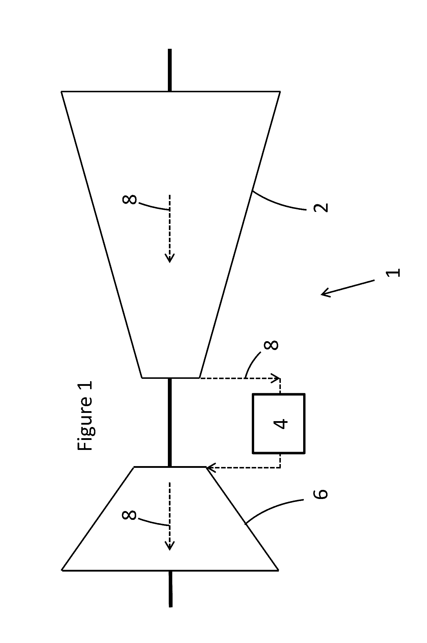
[0037]FIG. 1 shows a gas turbine 1 comprising a compressor 2, a combustor 4 downstream from the compressor 2 in a gas flow direction 8 and a turbine 6 downstream from the combustor 4 in the gas flow direction 8.

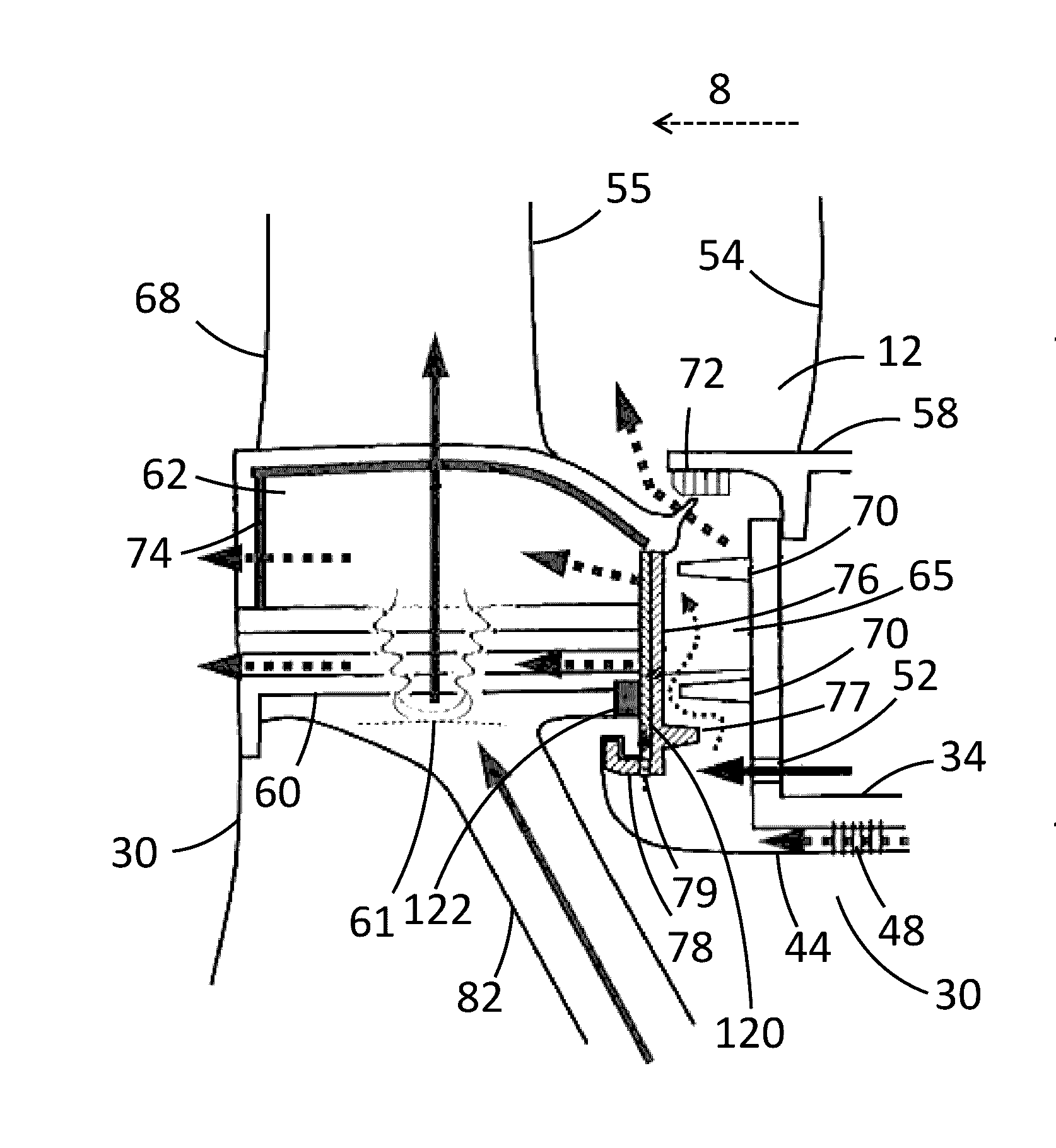
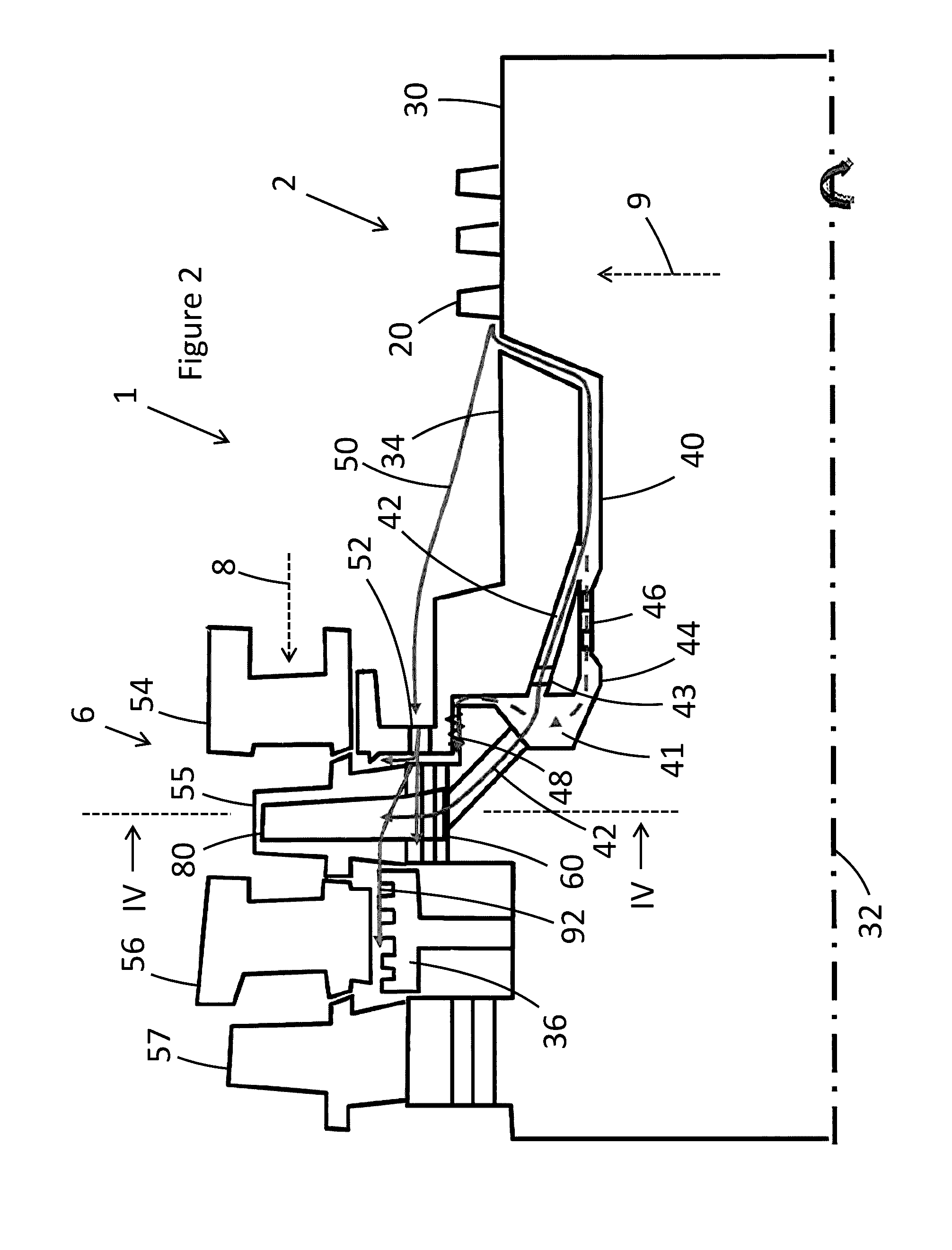
[0038]FIG. 2 shows a gas turbine 1 in more detail. The compressor 2 comprises a plurality of blades 20 and vanes (not shown). A rotor 30 (rotor drum) extends along a rotation axis 32 of the gas turbine 1. A rotor casing 34 (rotor cover) extends around the rotor 30.

[0039]A stator cooling air path 50 is configured and arranged to direct cooling air from the compressor 2 to the turbine blade 55; the exact path taken is not shown. A pre-swirl nozzle 52 is arranged in the stator cooling air path in the rotor casing 34. The stator cooling air path could alternatively or additionally pass through a first vane 54.

[0040]The turbine 6 comprises the first vane (vane 1) 54, a first blade 55 (blade 1), a second vane 56 (vane 2) and a second blade 57 (blade 2). The first blade 55 comprises...


PUM


Abstract

A gas turbine having a compressor, a combustor downstream from the compressor in a gas flow direction, and a turbine downstream from the combustor in the gas flow direction is described herein. The turbine includes a rotating part and a stationary part arranged around the rotating part. A gap between the rotating part and the stationary part, extends in a substantially radial direction relative to the rotation axis of the rotating part. A cooling fluid flows from the compressor to the gap, wherein at least a part of the cooling path extends in the stationary part, and wherein a pre-swirl nozzle is arranged adjacent to the gap and within the cooling path in the stationary part.

Description

TECHNICAL FIELD[0001]The present disclosure relates to gas turbines comprising cooling paths, and particularly to gas turbines comprising a cooling path with a pre-swirl nozzle arranged adjacent to a gap extending between the first blade and the rotor casing.BACKGROUND OF THE INVENTION[0002]State-of-the-art gas turbines, particularly the heavy-duty gas turbines used to generate a significant percentage of the world's energy supply, require a substantial amount of cooling to stop various components from melting.[0003]An area of particular importance in terms of cooling is the first blade in the turbine of a gas turbine. In addition to being subjected to very high temperatures, the first blade is also subject to high mechanical load due to rotation.[0004]The root of the first blade is a fir tree, and the fir tree is attached to the rotor of the gas turbine. The combination of high temperature and high load tends to limit the lifetime of the fir tree. As a result it has been appreciate...

Claims


Application Information

Patent Timeline
Patent Type & Authority Applications(United States)
IPC IPC(8): F01D5/18F02C7/12F02C3/04F01D5/30F01D11/02
CPCF01D5/187F01D5/3007F01D11/02F05D2260/2212F02C7/12F05D2220/32F02C3/04F01D5/30F01D25/12F01D5/082F01D11/001F05D2260/14Y02E20/16
Inventor RIAZANTSEV, SERGEIROFKA, STEFANMARMILIC, ROBERTKNOPFEL, HANSPETERSHCHUKIN, SERGEY
Owner ANSALDO ENERGIA SWITZERLAND AG
Why Eureka
Try Eureka