Ergonomic non-motorized vibratory concrete screed

a non-motorized, vibratory technology, applied in the field of concrete work, can solve the problems of common back and or arm strain or injury, vibratory screeds, and productivity decline, and achieve the effect of convenient interchangeability

Active Publication Date: 2016-02-23
ANGEL JEFF R
View PDF30 Cites 1 Cited by
  • Summary
  • Abstract
  • Description
  • Claims
  • Application Information

AI Technical Summary

Benefits of technology

[0028]According to one presently preferred embodiment, an ergonomic, floating, screeding, concrete-striking tool is provided that utilizes two screed bars bracketed together into a screed plate assembly, employing a waist-level U-shaped handle attached to the brackets at a 45 degree angle, adjustable to the operator's comfort. It is pulled across just poured, plastic concrete by an operator using short and repetitive pulling motions. The screed plate assembly surface, when properly used, produces a highly satisfactory, flat surface with no need for attached motorized vibration and with an ergonomic design that decreases physical stress on the operator to healthy levels when compared to the traditional stoop and drag 2×4 method. This tool does away with stooped striking altogether. This tool also does away with part of the form boards needed when using a single-bar standing screed that merely pulls concrete into a level surface. With the present invention, forms are not required on both sides of the striking surface; it “floats” on a “wet bench”. It creates very strong concrete because of operator-induced vibration which is increased in magnitude by the action of the double bar screed plate assembly. When the leading screed bar of the screed-plate assembly contacts the plastic concrete and is pulled, it creates a hydraulic change in the plastic concrete by compressing and forcing it down under the first screed bar and upward between the screed bars. As the short, repetitive pulls continue, the following screed bar of the screed plate assembly is able to cut, level, vibrate and consolidate the concrete a second time. This tool is simple to assemble and disassemble, store and maintain and is economical. It can be easily modified in size to accommodate the size of the concrete pour and be used by one man or a team. It also may eliminate the necessity for the magnesium floating process traditionally employed after screeding which pulls the fine granules of the concrete aggregate to the top, as this is already accomplished by the following edge of the double-barred strike plate of the present invention.
[0029]According to one aspect of the present invention, there is provided a vibratory concrete leveling device comprising a bracket assembly having an upper surface and a lower surface. The lower surface of the bracket assembly includes a plurality of spaced apart slots, each spaced apart slot extending across a width of the bracket assembly. A plurality of screed bars corresponding to and positioned in the plurality of spaced apart slots are also provided. Each of the plurality of screed bars are loosely fitted into each corresponding slot to promote vibratory action during use. An elongated handle is also provided having a first end attached to the bracket assembly and a second end for grasping by a user. The width of each of the plurality of spaced apart slots is greater than the width of each of the corresponding plurality of screed bars.

Problems solved by technology

A screed bar can also be used by a single individual, but productivity is decreased as compared to that of a two-person team due to the increased physical effort required.
Using screed bars in this fashion is a common source of back and or arm strain or injury.
Motorized vibratory screeds of any type are highly technical pieces of equipment, which are costly, heavy, and require working technical knowledge of the specific tool used.
The traditional manual screeding technique described above is laborious, and frustrating at times, as well.
Standing improves the operator's ergonomics but the device can only screed the concrete without the ability to introduce vibration into the concrete without the addition of a motor strapped to the device.
The motorized floating vibratory screed is expensive, often highly technical, and heavy.
Transportation of large screeds for larger pours becomes an issue for a small-business contractor who often operates with a skeleton crew.
The expense of moving a heavy, unwieldy piece of equipment like a motorized screed must be considered.
Larger vehicles with winch capabilities increase cost.
Electronic equipment requires expensive repairs and oftentimes, extensive down time.
All of these factors can greatly increase frustration and decrease productivity if any one fails at any given time.

Method used


Image

  • Ergonomic non-motorized vibratory concrete screed
  • Ergonomic non-motorized vibratory concrete screed
  • Ergonomic non-motorized vibratory concrete screed

Examples


Embodiment Construction

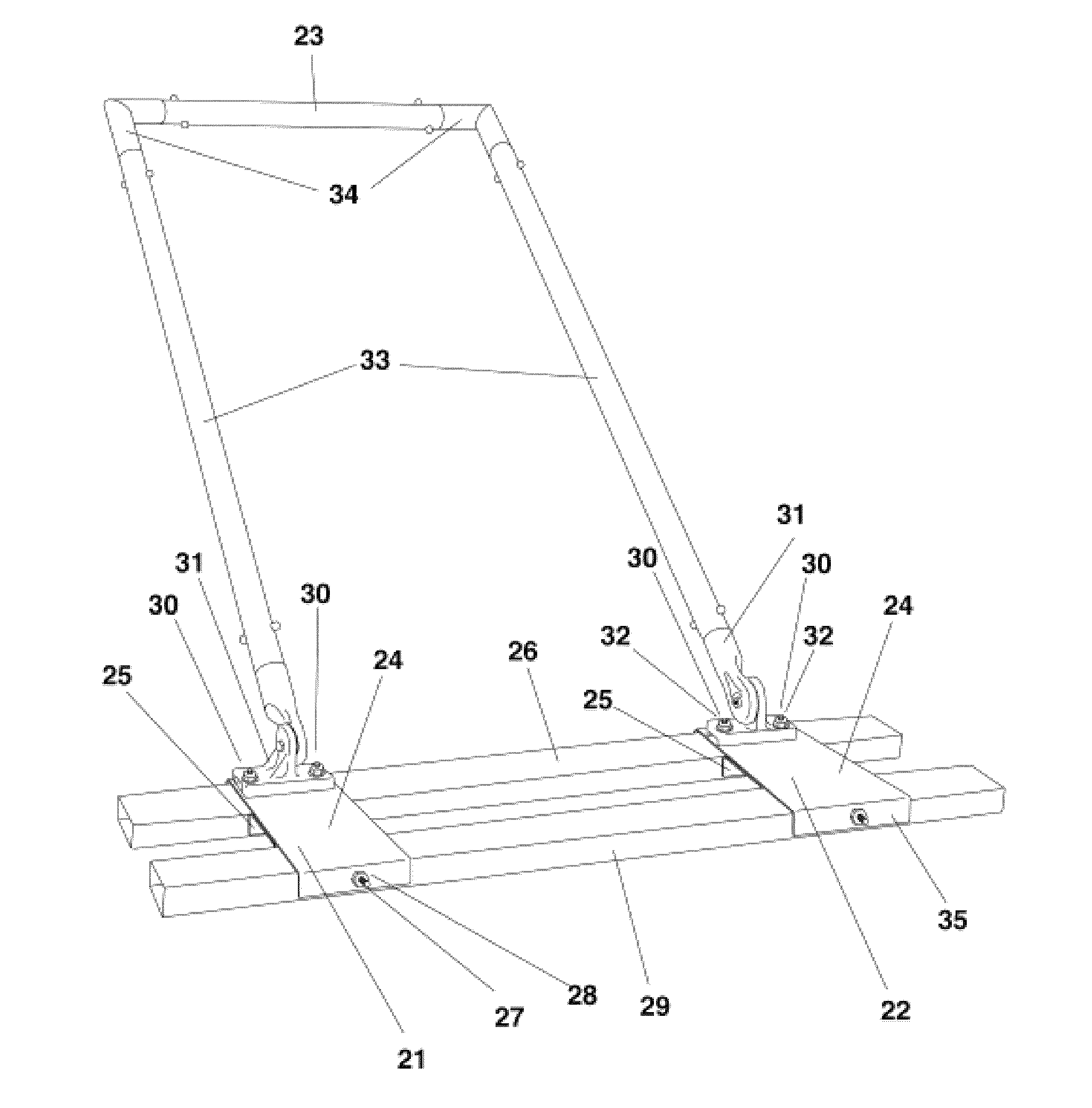
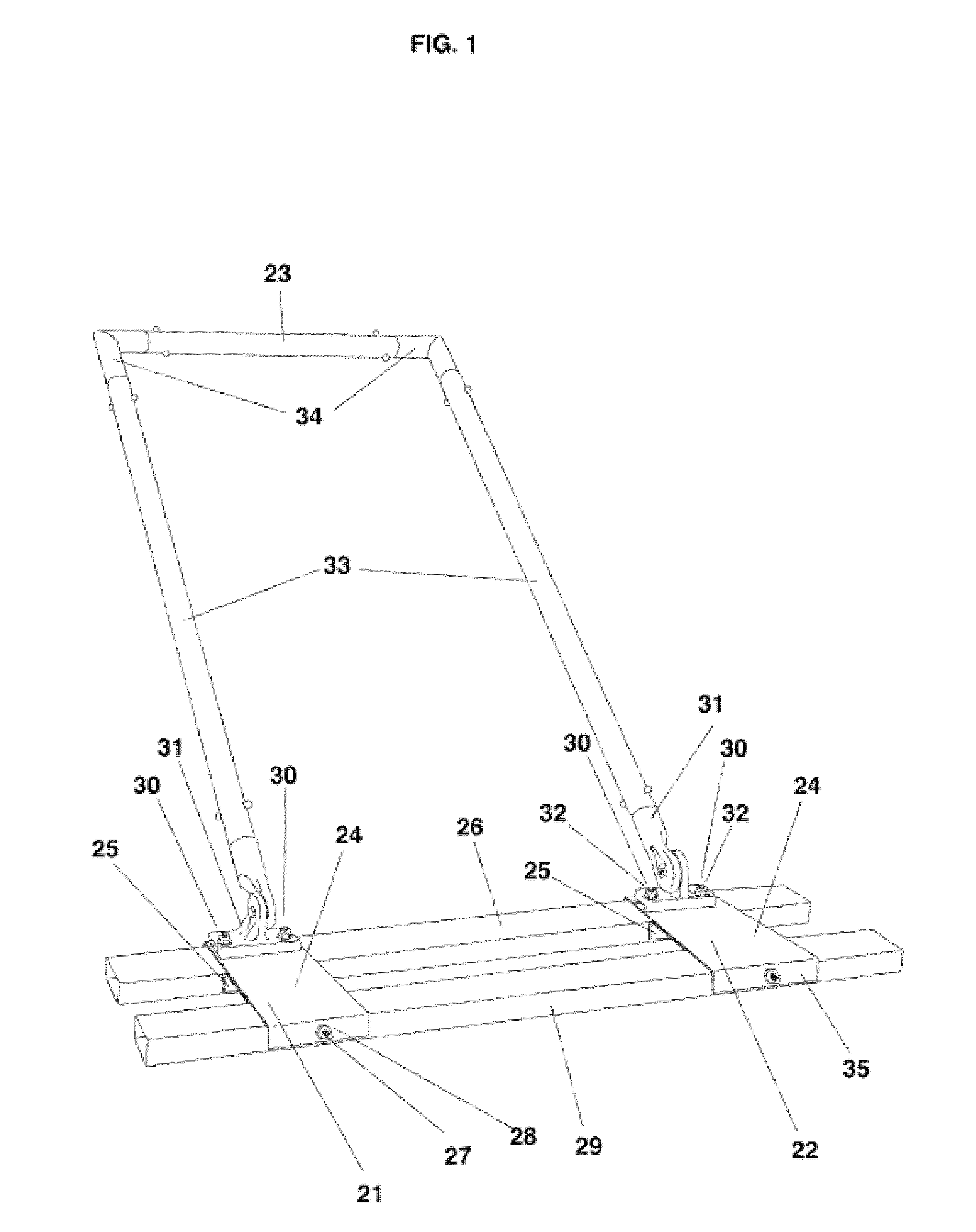
[0040]One presently preferred embodiment of the invention is illustrated in FIG. 1. The powerful effects of this simple screed originate in the floating screed plate assembly which is comprised of two screed bars linked by a bracket system. There is a right 21, and a left 22, bracket assembly. These brackets are designed for the attachment of the handle 33, for the operator and attachments of the floating screed plate assembly that contacts the concrete. Each bracket assembly comprises two separate metal components: an inverted U-shaped upper bracket 24, and an inverted U-shaped lower bracket 25. The right and left upper brackets 24, are 8″×13″ and made of light-gauge metal. The right and left lower brackets, 25, are 8″×5″ with both front and rear downward L-bends of 90°, hereafter, “flanges” being 8″×1⅜″ on surface. When assembled, this bracket assembly provides two spaces: one space for the leading and one space for the following planar-oriented 2″×4″ strike bars of the floating s...


PUM


Abstract

An ergonomic non-motorized vibratory concrete screed is provided that is designed to be used in the fashion of a standing one-man wet screed having a double barred, floating strike plate oriented in a planar fashion with which to strike and consolidate a concrete slab surface. The vibratory concrete leveling device according to the invention includes a bracket assembly having an upper surface and a lower surface. The lower surface of the bracket assembly includes a plurality of spaced apart slots, each spaced apart slot extending across a width of the bracket assembly. A corresponding plurality of screed bars are removably positioned in the plurality of spaced apart slots. Each of the plurality of screed bars are loosely fitted into each corresponding slot to promote vibratory action during use. An elongated handle is provided having a first end attached to the bracket assembly and a second end for grasping by a user.

Description

FIELD OF THE INVENTION[0001]This application relates to concrete work, specifically striking, screeding and floating horizontal concrete surfaces.BACKGROUND OF THE INVENTION[0002]When a concrete contractor is asked to pour a sidewalk, concrete pad, or floor, once the plastic concrete has been poured into its forms and raked level, the contractor must produce a flat, uniform surface that is structurally sound and satisfactory to the customer.[0003]Concrete “flatwork” is a universal process where, first, the concrete contractor pours plastic concrete into forms, then levels the plastic concrete using hand labor. Hand labor is used to place and roughly level the plastic concrete using tools called come-alongs or rakes. The next step is called “striking” the concrete. Concrete is “struck” using a screed; it is given a flat, level surface using a horizontally-aligned bar of some type to pull and level the freshly poured plastic concrete surface into a plane.[0004]Traditionally, striking ...

Claims


Application Information

Patent Timeline
Patent Type & Authority Patents(United States)
IPC IPC(8): E01C19/22E04G21/06E04F21/24E01C19/40
CPCE01C19/402E04F21/242E04G21/066E04F21/241
Inventor ANGEL, JEFF, R.
Owner ANGEL JEFF R
Why Eureka
Try Eureka